English
 русский
 عربى
عربى
Get in touch
Get in touch
Jun 25, 2025
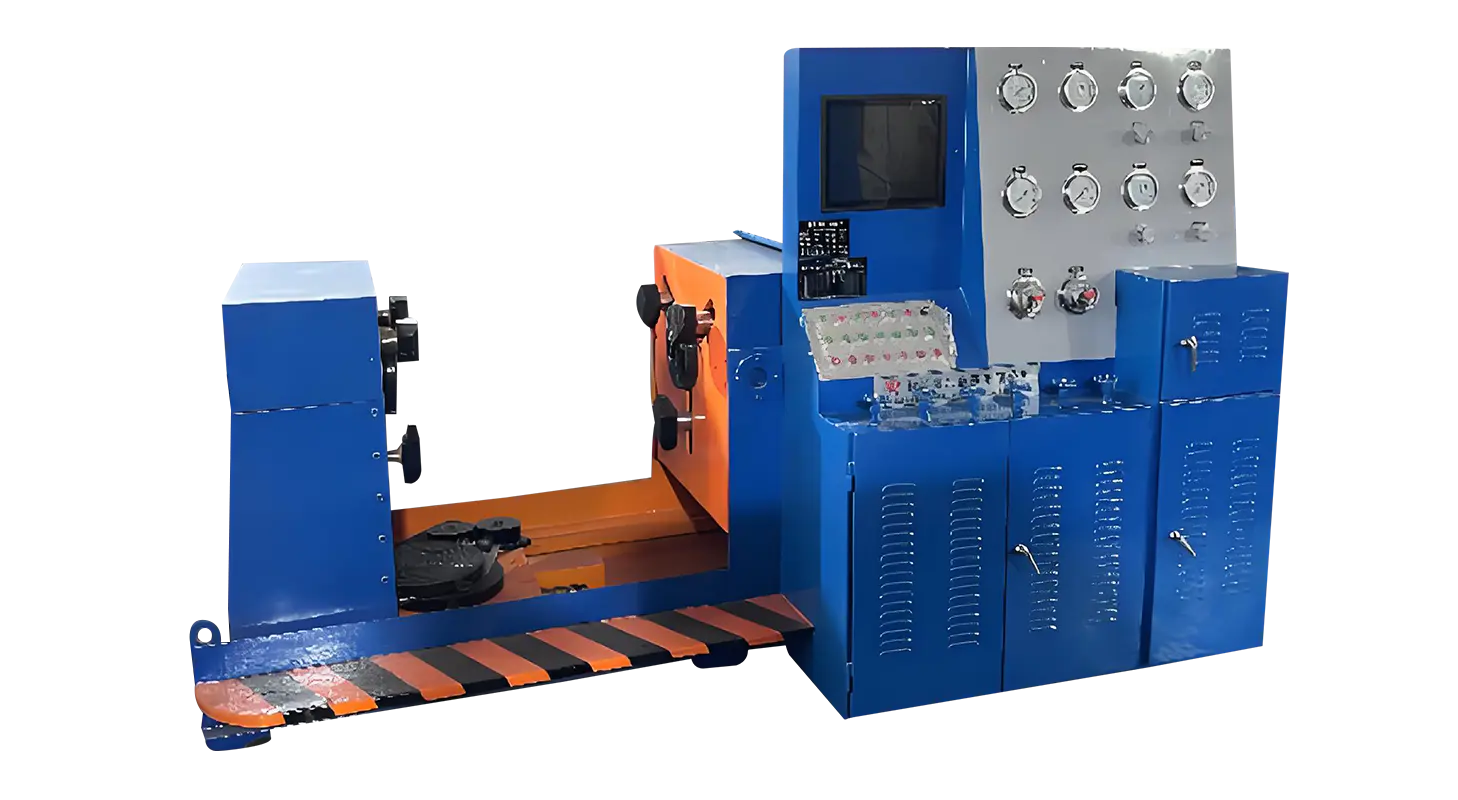
Hydraulic valve test benches play a critical role in ensuring the reliability and safety of various types of valves used in industrial applications. These test benches are designed to simulate real operating conditions to evaluate the performance, durability, and functionality of hydraulic valves. In this article, we will explore the working principle of hydraulic valve test benches, focusing on the processes involved in solenoid valve testing machines and testing a pressure relief valve.
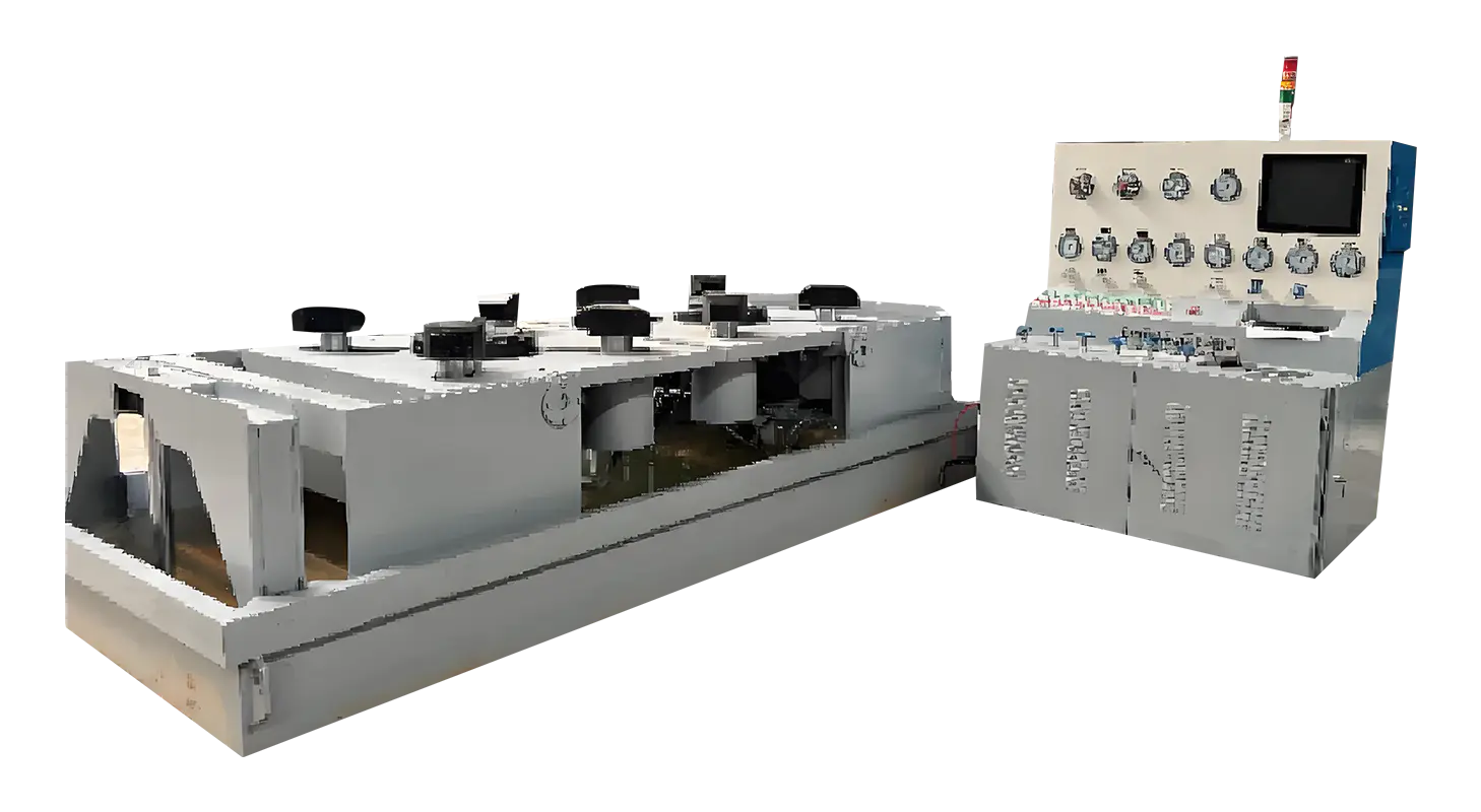
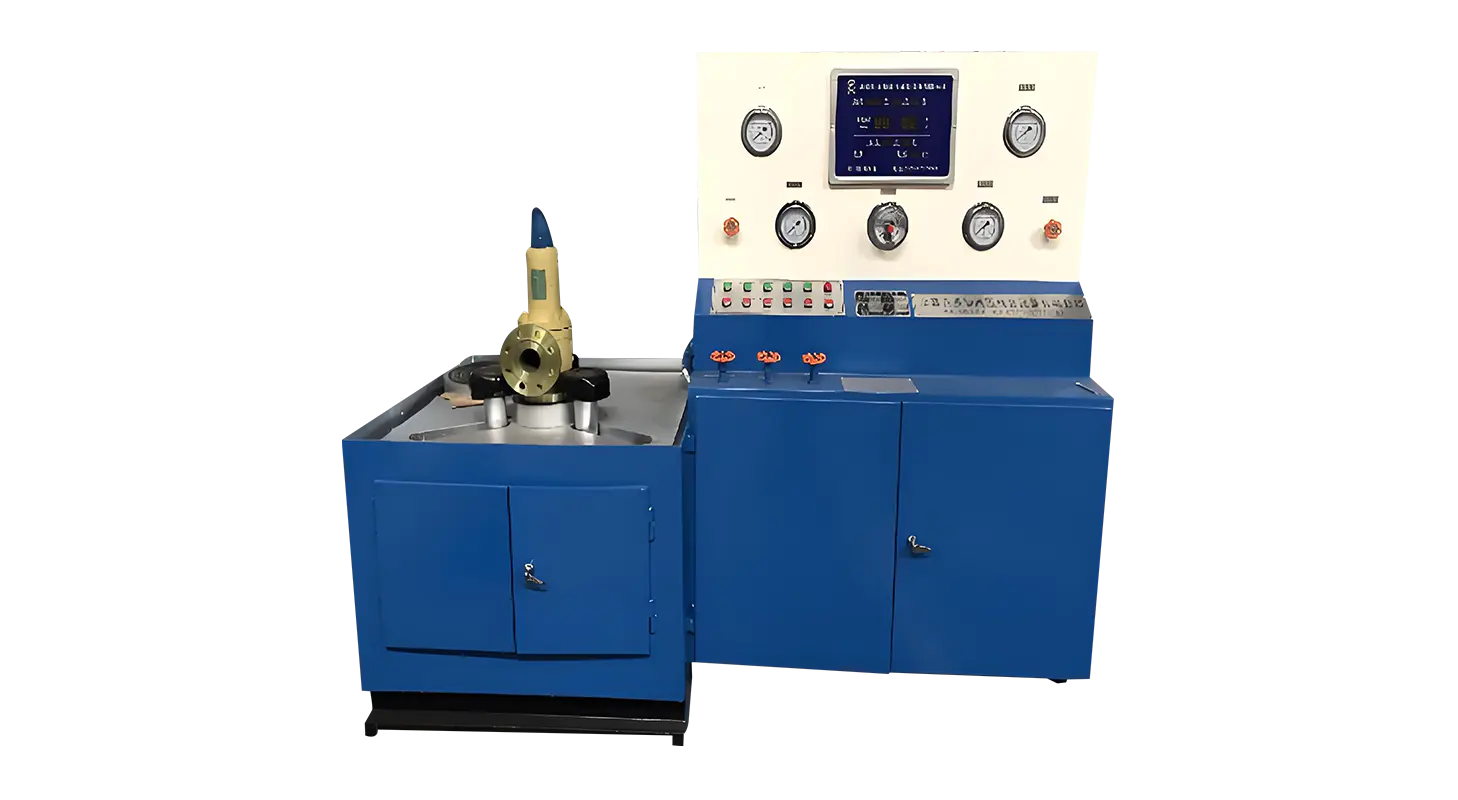
A hydraulic valve test bench typically consists of a hydraulic power unit, control system, measuring instruments, and the test fixture where the valve is mounted. The main objective is to create controlled pressure and flow conditions that replicate the valve’s working environment. By doing so, the test bench can verify if the valve performs according to specified standards and if it maintains proper sealing, responsiveness, and pressure regulation.
At the core of the hydraulic valve test bench is the hydraulic power unit, which supplies pressurized fluid to the valve under test. The fluid pressure and flow rate are precisely controlled using pumps, valves, and sensors integrated into the system. During testing, the valve is subjected to different pressure levels and flow conditions to assess its behavior under various scenarios.
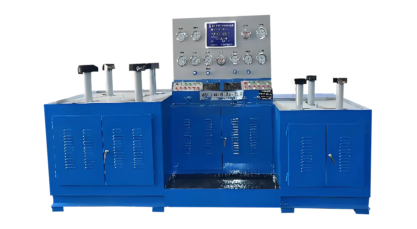
One common type of valve tested on hydraulic benches is the solenoid valve. A solenoid valve testing machine is specifically designed to evaluate the functionality of solenoid valves by applying electrical signals to actuate the valve and simultaneously monitoring its hydraulic response. These machines measure parameters such as response time, leakage, and pressure holding capability. Testing solenoid valves involves checking the valve’s ability to open and close reliably when energized or de-energized, ensuring that it responds correctly within the hydraulic circuit.
The solenoid valve testing process begins with mounting the valve securely on the test bench. The hydraulic system is then activated to apply the required pressure. An electrical control module sends signals to the solenoid coil, causing the valve to actuate. Sensors record the valve’s response, including the speed of operation and any leakage detected during the closed state. This testing helps identify manufacturing defects or operational issues that could affect system performance once the valve is installed in the field.
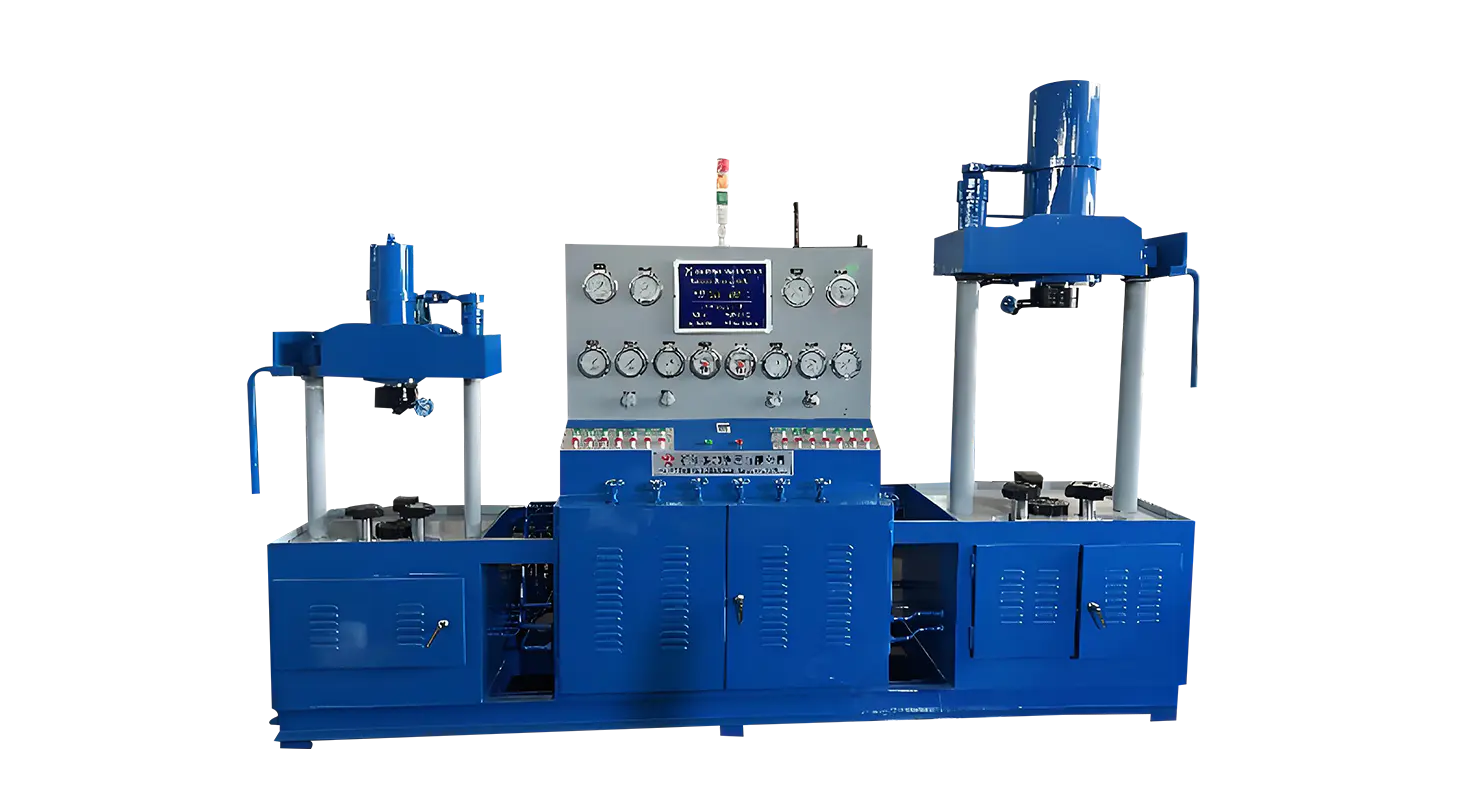
Another important valve type tested on hydraulic test benches is the pressure relief valve. Testing a pressure relief valve involves verifying that the valve opens at the designated pressure to protect the hydraulic system from overpressure conditions. The test bench gradually increases the pressure until the valve begins to open, measuring the opening pressure, flow rate, and closing pressure.
The process of testing a pressure relief valve begins by installing the valve on the test fixture and connecting it to the hydraulic circuit. The hydraulic power unit gradually raises the pressure, and pressure sensors continuously monitor the system. Once the valve reaches its set pressure, it should open to release fluid, thereby preventing damage to the hydraulic system. The test bench records the pressure at which the valve opens and closes, ensuring the valve operates within specified limits. Any deviation from these parameters could indicate the need for valve adjustment or replacement.
In addition to testing opening pressures, the hydraulic valve test bench also evaluates the valve’s ability to reseat properly after releasing pressure. This reseating capability is crucial for maintaining system stability and avoiding continuous fluid loss. The test bench checks for leakage when the valve is in the closed position, which is vital for efficient hydraulic system operation.
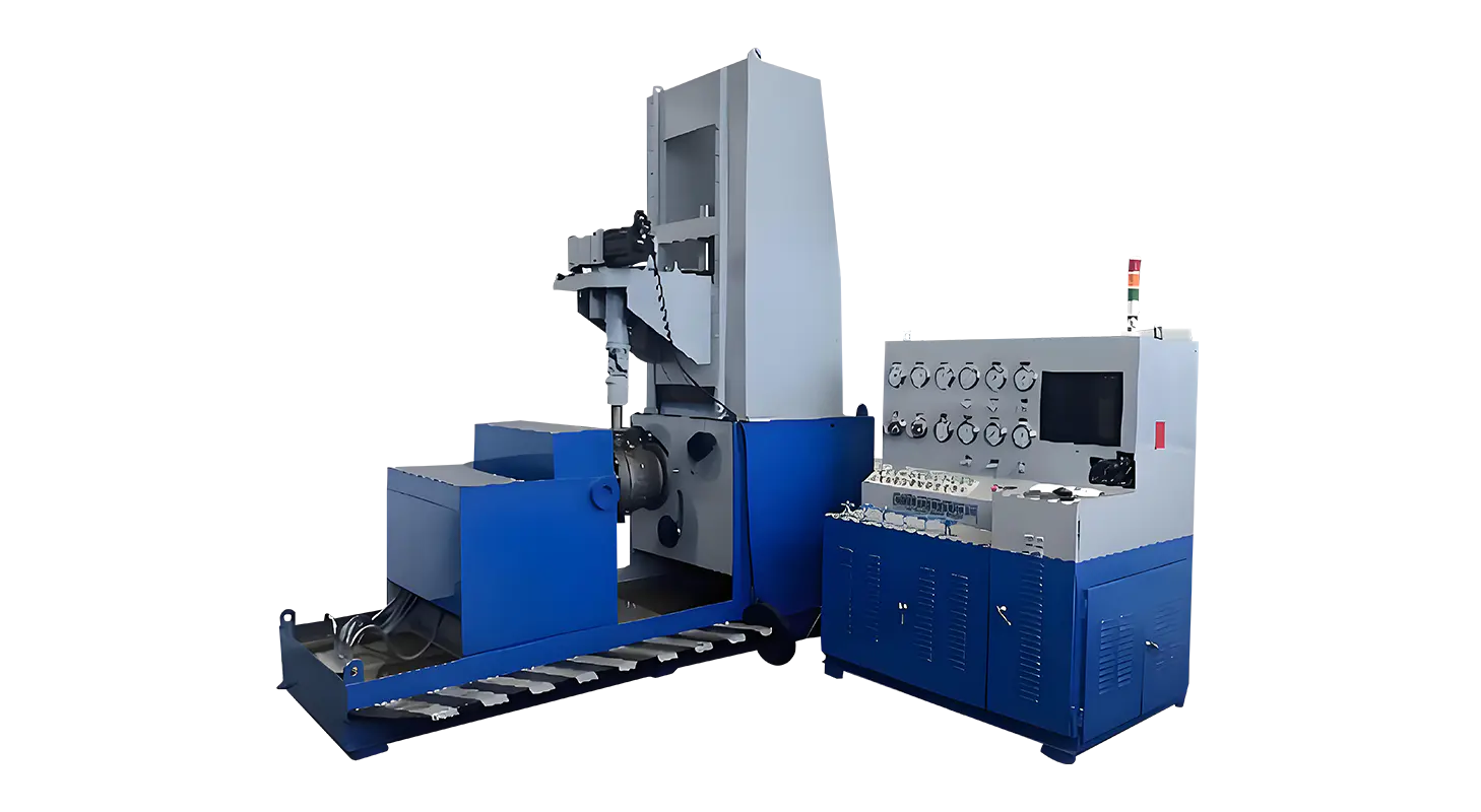
Hydraulic valve test benches are equipped with control systems that automate the testing process, allowing for consistent and repeatable tests. Data acquisition systems collect and store measurement data for analysis, enabling technicians to make informed decisions about valve quality and performance. Some advanced test benches allow customization of test parameters to accommodate different valve sizes, types, and standards.
Maintenance of the hydraulic valve test bench is also important to ensure accurate and reliable testing. Regular calibration of sensors and inspection of hydraulic components help maintain the precision of the testing process. Ensuring the cleanliness of the hydraulic fluid and checking for leaks in the system contribute to consistent test results.
In conclusion, hydraulic valve test benches provide an essential function in verifying the operational readiness of hydraulic valves. Whether it is using a solenoid valve testing machine to confirm electrical and hydraulic actuation or testing a pressure relief valve to ensure proper pressure regulation, these benches simulate real-world conditions to validate valve performance. Understanding the working principle of hydraulic valve test benches helps manufacturers and end-users maintain valve quality, improve system safety, and reduce the risk of failures in hydraulic applications.
Related Products
Contact us
Address
Sanqiao Industrial Zone, Oubei, Yongjia County, Zhejiang Province, China
Phone
+86-13676520568
Telephone number
+86-13676520568
Fax
products
Quick Links
QR CODE