English
 русский
 عربى
عربى
Get in touch
Get in touch
Oct 24, 2025
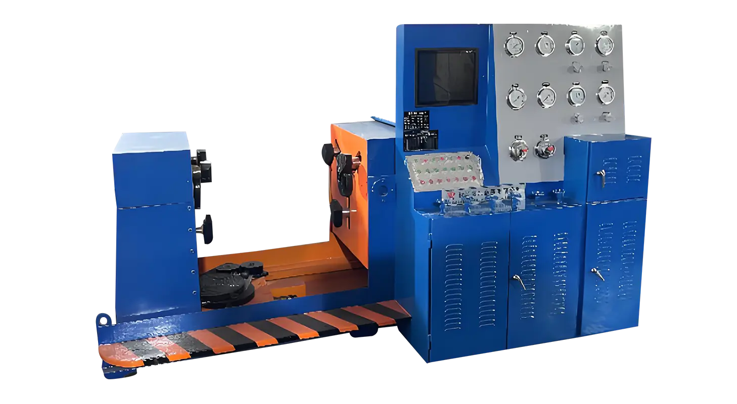
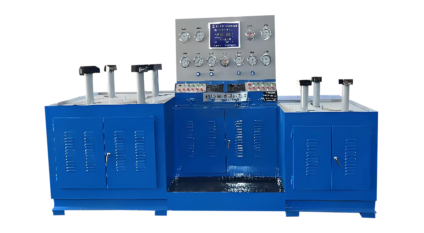
Across industrial testing facilities, equipment design plays a critical role in ensuring safe and precise operations. A Ball Valve Test Bench provides a controlled environment for checking sealing performance and pressure endurance, while a well-developed Valve Test Bench Design defines the methods for switching between water and gas testing. Among these procedures, gas testing requires a clear sequence of steps and attention to detail, since it involves handling a compressible medium under high pressure.
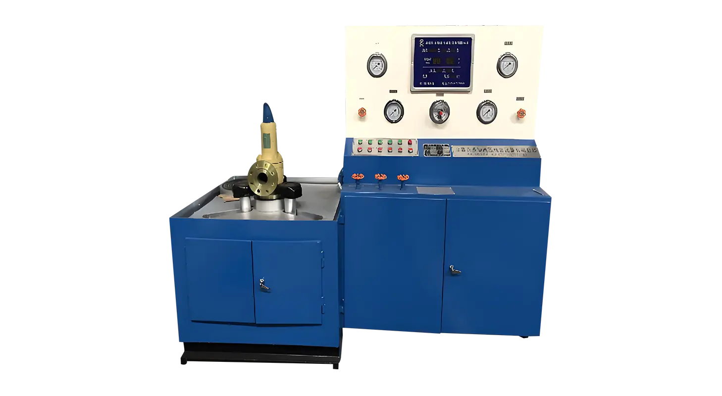
Before testing begins, the valve must be securely mounted on the bench. Hydraulic clamping systems are often used, allowing controlled radial and axial pressure to lock the flange or threaded ends in place. This prevents external forces from influencing the test results. Operators typically refer to a pressure chart to adjust clamping force appropriately, ensuring stability during testing. At this stage, the water discharge line should remain closed, while the gas inlet system is prepared for activation.
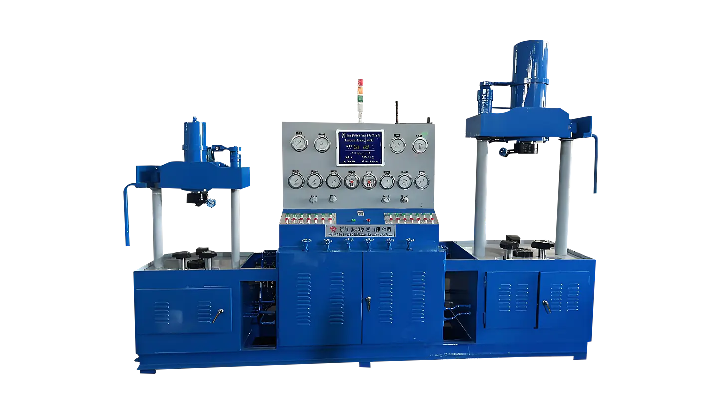
A critical step involves configuring the electronic control pressure gauge. For gas testing, the target pressure can range up to 16.0 MPa, depending on the specification of the valve being examined. Multiple gauges are included in modern systems to cover different ranges such as micro, low, medium, and high pressure, ensuring accuracy across test conditions. Establishing the correct parameters before gas pressurization begins prevents overloading and maintains safety standards.
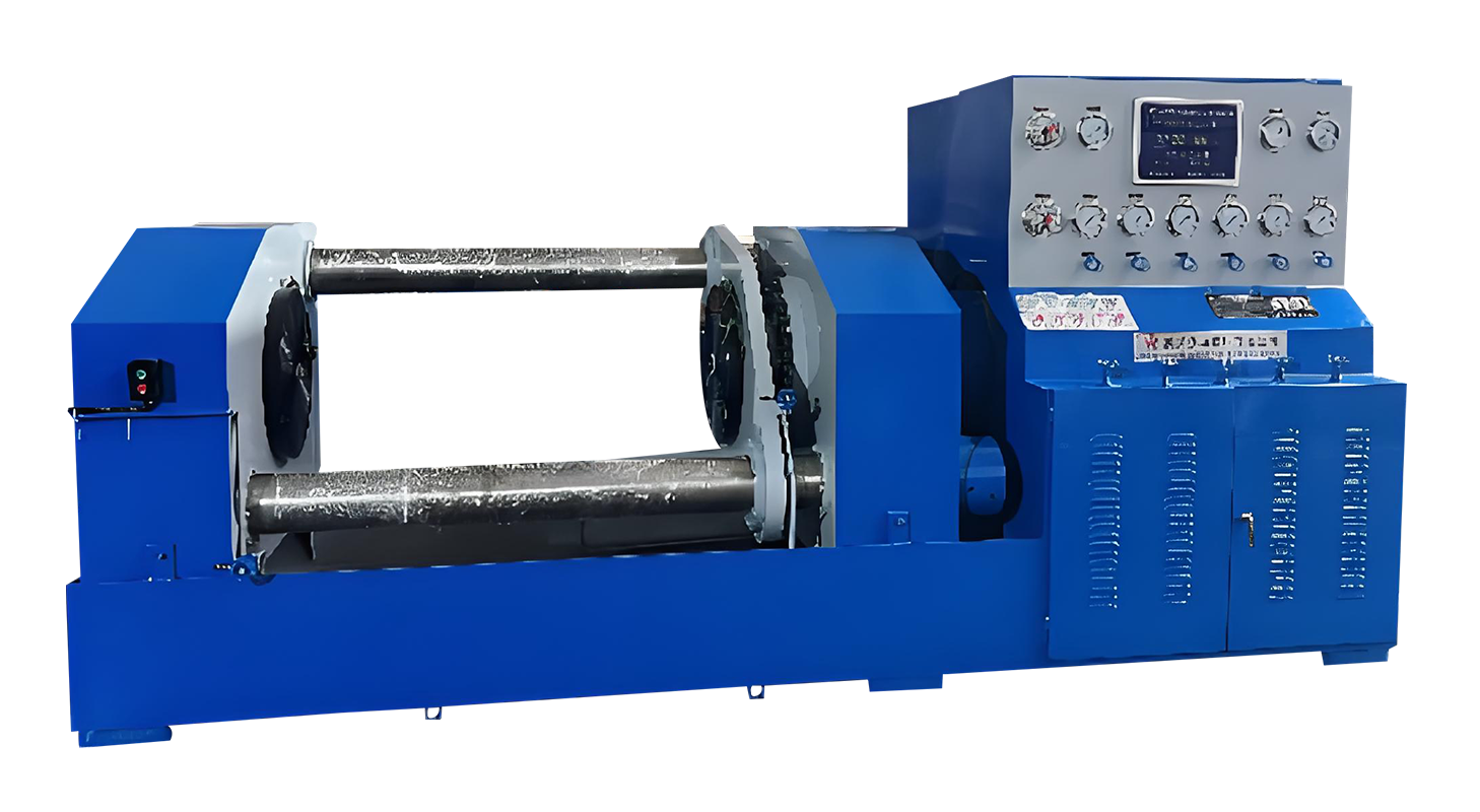
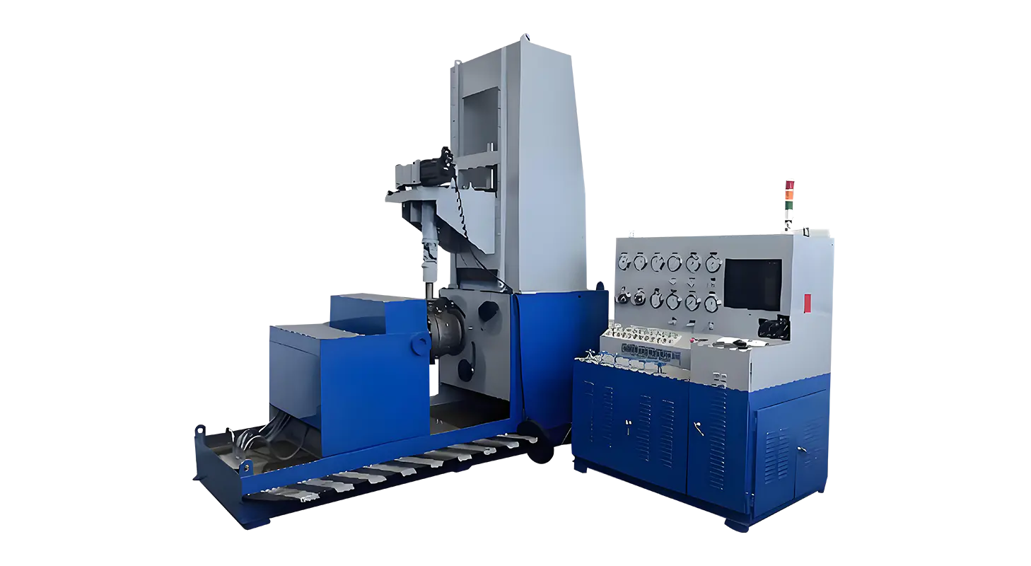
Once the valve is clamped and pressure settings are established, the operator opens the gas inlet valve. The gas boosting system, driven by compressed air, gradually increases pressure inside the valve cavity. A pre-stabilization tank is usually incorporated into the system, allowing charging up to around 3.0–5.0 MPa before the booster pump takes over. This staged approach avoids sudden pressure spikes that could damage components or create unsafe conditions. Operators are instructed not to exceed the charging limit during this phase, as rapid overfilling may compromise equipment integrity.
When the desired pressure is reached, the system automatically transitions into a hold mode. This allows the operator to observe the valve under stable conditions and assess sealing performance. Leakage checks are conducted visually or through monitoring equipment, depending on the level of automation built into the bench. Maintaining steady pressure over a defined time period provides reliable data on whether the valve can sustain the designated operating conditions without fault.
At the conclusion of the observation period, the pressure inside the cavity must be reduced to zero before the valve can be removed. The operator achieves this by gradually opening the gas discharge valve. The zero-pressure release mechanism, integrated into modern benches, ensures that clamping jaws cannot disengage until all internal pressure has been fully released. This safeguard protects operators from accidental exposure to residual pressure and prevents mechanical strain on the test components.
Throughout the procedure, operators rely on multiple gauges to confirm stability. High precision instruments for different pressure ranges are installed to minimize error and provide clear readings. In many cases, electronic data acquisition systems or PLC-based controls are integrated, recording test parameters for traceability and compliance with quality standards. This structured monitoring ensures both consistency and accountability during every gas test cycle.
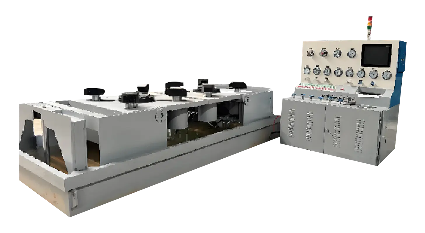
Gas testing can involve additional risks compared to water testing, which is why optional safety modules are available in many bench configurations. Protective enclosures or safety doors may be added to contain any unexpected release of gas. Automated control sequences, including programmable pressure cycles and digital leak detection sensors, reduce the need for manual intervention. These additions enhance operational safety while simplifying test management for frequent or high-volume applications.
By following structured steps—mounting, pressure configuration, controlled boosting, holding, and safe depressurization—operators can ensure that gas testing on a Ball Valve Test Bench is both accurate and secure. A modern Valve Test Bench Design brings together hydraulic clamping, precision monitoring, and safety interlocks to support consistent results, making gas testing a practical and dependable process across industries.
Related Products
Contact us
Address
Sanqiao Industrial Zone, Oubei, Yongjia County, Zhejiang Province, China
Phone
+86-13676520568
Telephone number
+86-13676520568
Fax
products
Quick Links
QR CODE