English
 русский
 عربى
عربى
Get in touch
Get in touch
May 08, 2026
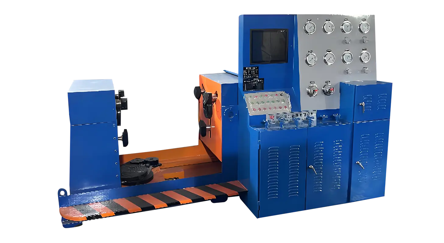
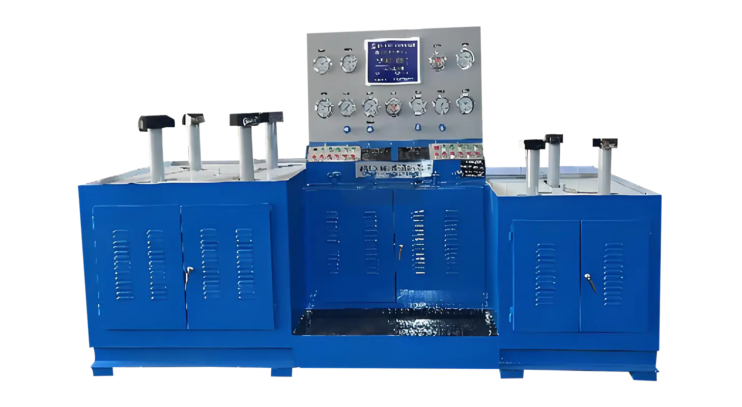
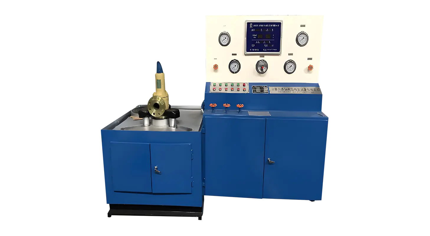
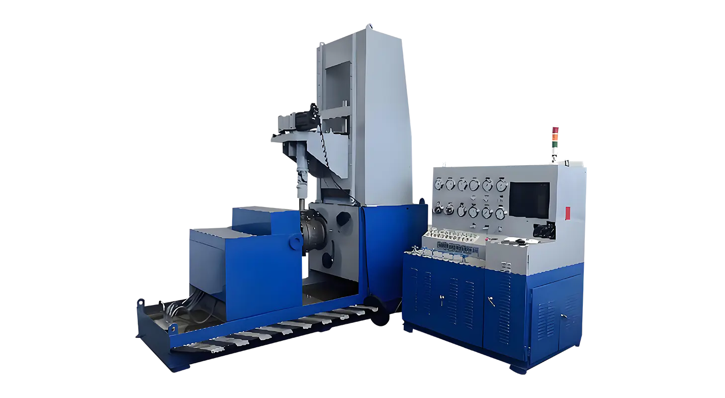
Valve Test Machine and Relief Valve Test Bench are widely used in hydraulic system verification workflows where sealing performance, pressure stability, and safety response need structured evaluation. In many industrial setups, these two testing systems are applied together to observe valve behavior under controlled pressure conditions and to record possible leakage or pressure relief patterns during operation cycles.
Hydraulic systems rely on stable pressure control to maintain safe and consistent operation. Even minor leakage or delayed relief response in a valve can affect system balance, increase maintenance frequency, or cause unexpected shutdowns in connected equipment. Traditional inspection methods often depended on manual observation or simplified pressure checks, which limited the ability to capture dynamic performance under varying load conditions.
As hydraulic applications expand across energy systems, manufacturing equipment, and fluid control networks, testing requirements have shifted toward more structured and repeatable methods. A Valve Test Machine is now commonly integrated into production and maintenance processes to simulate working pressure conditions, while a Relief Valve Test Bench focuses on verifying opening pressure, reseating performance, and pressure release stability under controlled environments.
These requirements are not limited to final product inspection. They are also used during component development, repair validation, and periodic system maintenance, where consistent measurement data is needed to understand valve behavior over time.
Recent testing setups place greater emphasis on controlled pressure regulation, digital monitoring, and modular compatibility. A Valve Test Machine is typically designed with multiple pressure channels, allowing operators to simulate different hydraulic conditions without changing hardware configurations. Meanwhile, a Relief Valve Test Bench is structured to focus specifically on safety valve response characteristics under incremental pressure increases.
Compared to earlier mechanical-only systems, current configurations often include sensor-based measurement and data logging functions. These allow users to track pressure curves and response timing with more consistency across repeated tests.
Key operational aspects often include:
A typical setup allows operators to switch between testing modes without extensive mechanical adjustment, which supports continuous workflow in maintenance workshops or production lines. Instead of focusing on a single test outcome, these systems provide a broader view of valve performance under multiple simulated conditions.
Valve testing equipment is used in multiple sectors where hydraulic control plays a central role. In manufacturing environments, it is commonly applied during quality inspection of newly produced valves before assembly into larger systems. In maintenance workshops, it is used to evaluate worn or repaired components to determine whether they meet operational requirements.
In energy-related systems such as hydraulic power stations or compressor units, Relief Valve Test Bench setups are often used to verify emergency pressure release functions. This helps confirm whether valves respond within expected pressure thresholds during abnormal system conditions.
Other common application areas include:
In each case, the testing process focuses on observing pressure response behavior rather than static measurements alone. This allows technicians to understand how valves behave under gradual pressure changes instead of single-point readings.
The following table outlines general functional differences and shared characteristics between the two systems:
|
Testing Aspect |
Valve Test Machine |
Relief Valve Test Bench |
|
Primary Focus |
General valve performance testing |
Pressure relief response testing |
|
Pressure Control Range |
Multi-level adjustable |
Incremental pressure build-up |
|
Data Recording |
Available in most configurations |
Common in advanced setups |
|
Application Scope |
Broad valve categories |
Safety and relief valves |
|
Operation Mode |
Multi-test cycle support |
Single-function focus testing |
This comparison reflects how both systems complement each other rather than replace one another. In practice, many testing environments use both to cover different aspects of hydraulic valve evaluation.
In a controlled testing environment, valve performance data is typically recorded in structured formats. Below is an example of how test parameters may be documented during a relief valve evaluation:
|
Test Item |
Measured Value Range |
Observation Notes |
|
Opening Pressure |
12–15 MPa |
Stable response during cycle |
|
Reseating Pressure |
10–13 MPa |
Gradual pressure return observed |
|
Leakage Observation |
Low to moderate |
Dependent on sealing condition |
|
Response Time |
0.3–0.6 seconds |
Consistent across repeated tests |
Such data is used for comparison across production batches or maintenance cycles. It also helps identify gradual performance changes that may not be visible during manual inspection.
The integration of Valve Test Machine and Relief Valve Test Bench systems reflects a broader shift toward data-based equipment management. Instead of relying on visual inspection alone, operators can now evaluate valve behavior through repeatable test cycles and recorded pressure profiles.
This approach supports long-term equipment monitoring strategies where performance trends are analyzed over time. For example, repeated testing results can indicate early signs of sealing degradation or delayed pressure response, allowing maintenance planning to be adjusted accordingly.
In addition, standardized testing procedures help reduce variation between different operators or testing environments. This contributes to more consistent evaluation results across different production or maintenance sites.
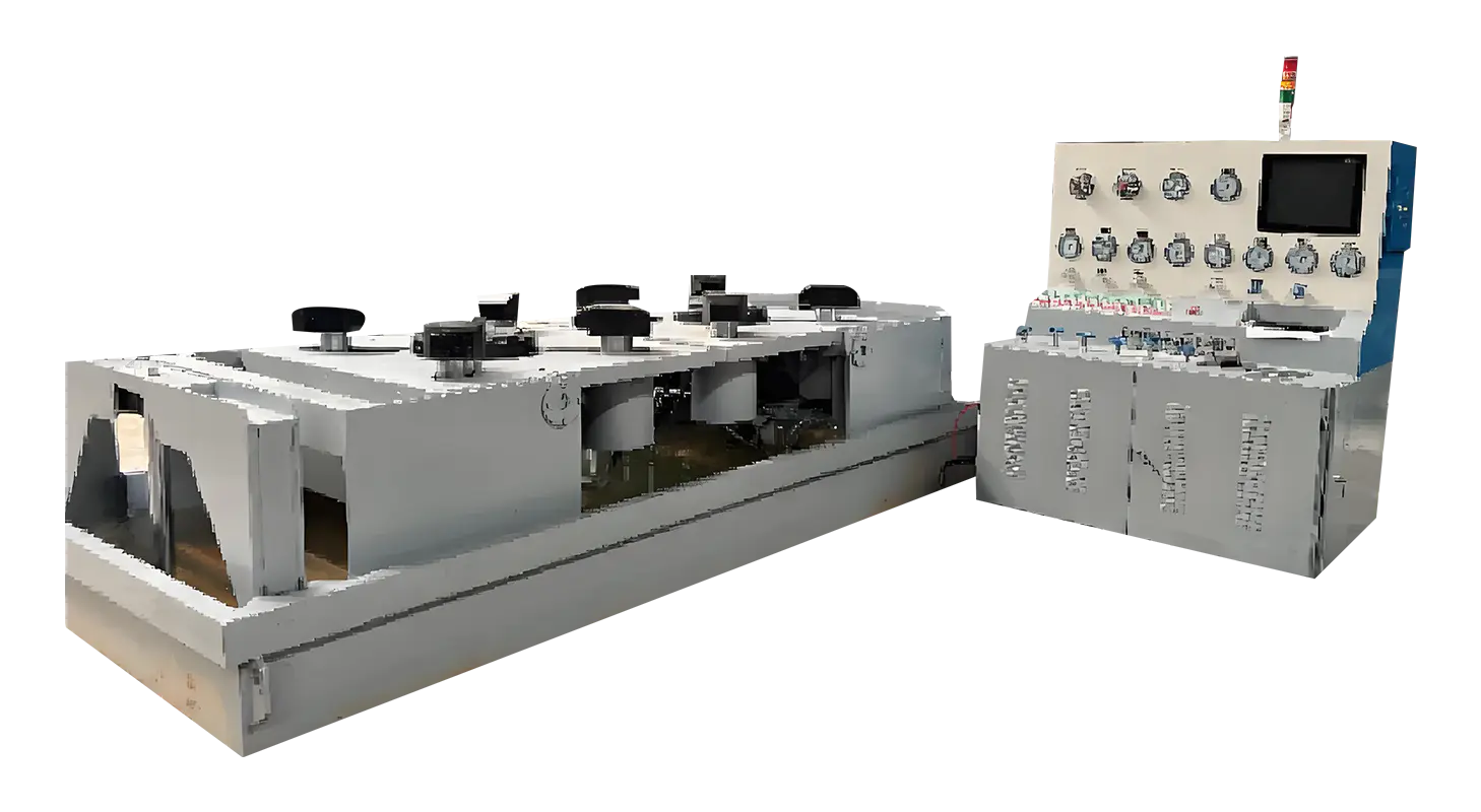
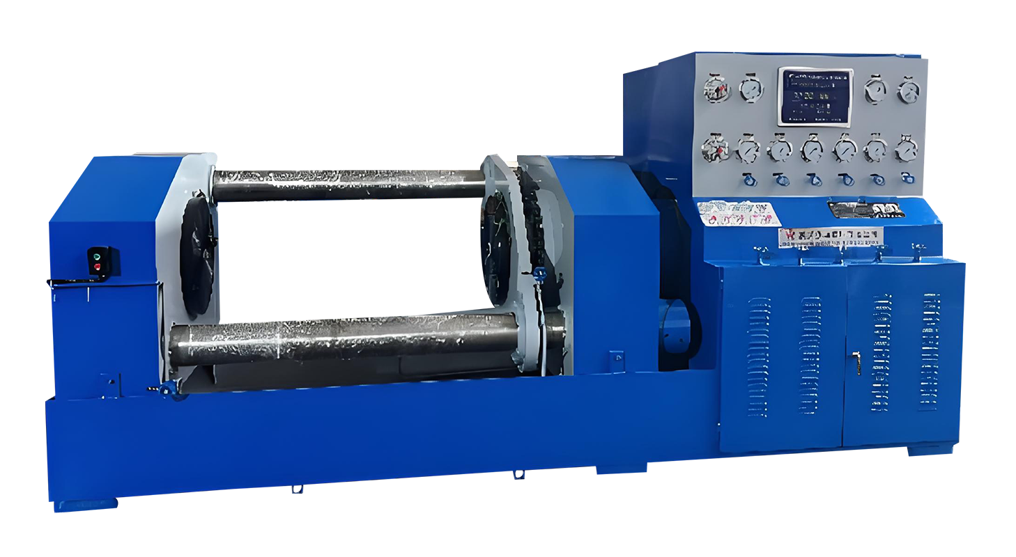
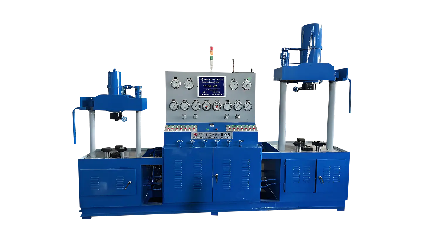
Related Products
Contact us
Address
Sanqiao Industrial Zone, Oubei, Yongjia County, Zhejiang Province, China
Phone
+86-13676520568
Telephone number
+86-13676520568
Fax
products
Quick Links
QR CODE