English
 русский
 عربى
عربى
Get in touch
Get in touch
Nov 14, 2025
Industrial valve testing often requires systems that can handle different pressure media under precise and controlled conditions. Both the Relief Valve Test Bench and the Hydraulic Valve Test Bench are designed to meet this demand, offering the ability to conduct accurate tests using water and gas. Understanding why these benches are suitable for dual media testing helps engineers and operators choose appropriate equipment for their calibration and inspection needs.
Valves used in industrial pipelines, energy facilities, and process systems may operate under liquid or gas pressure, and each medium presents unique testing challenges. Water testing allows clear visualization of leaks and offers stable pressure control, while gas testing simulates real operating environments for valves handling compressed air, steam, or gas mixtures. A testing system capable of switching between these two media efficiently can therefore provide a more complete evaluation of valve performance.
Dual media testing not only verifies the opening and closing pressures of relief valves but also assesses sealing performance and stability under variable conditions. The ability to use both water and gas within a single system saves time, reduces the need for multiple testing setups, and ensures consistent data collection.
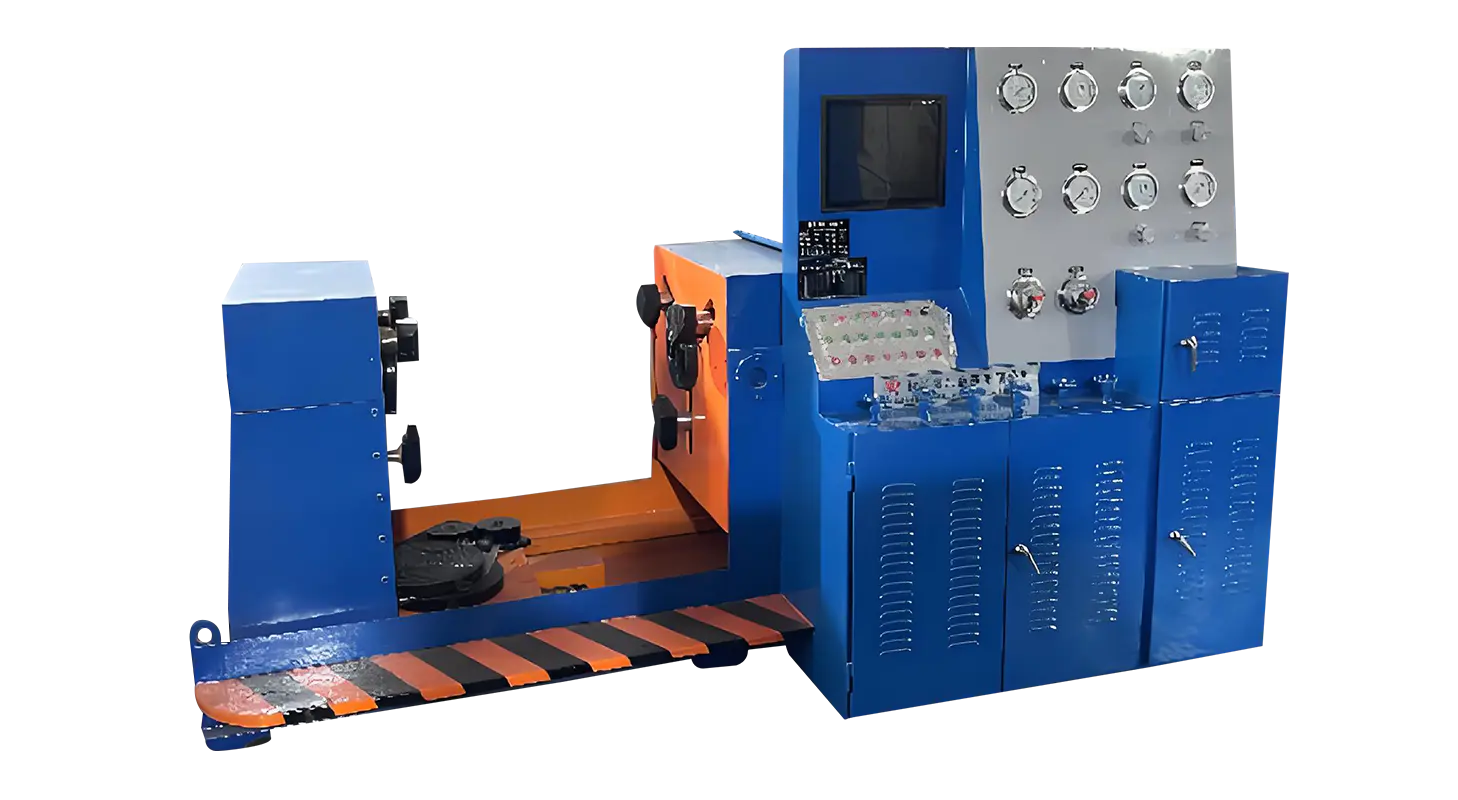
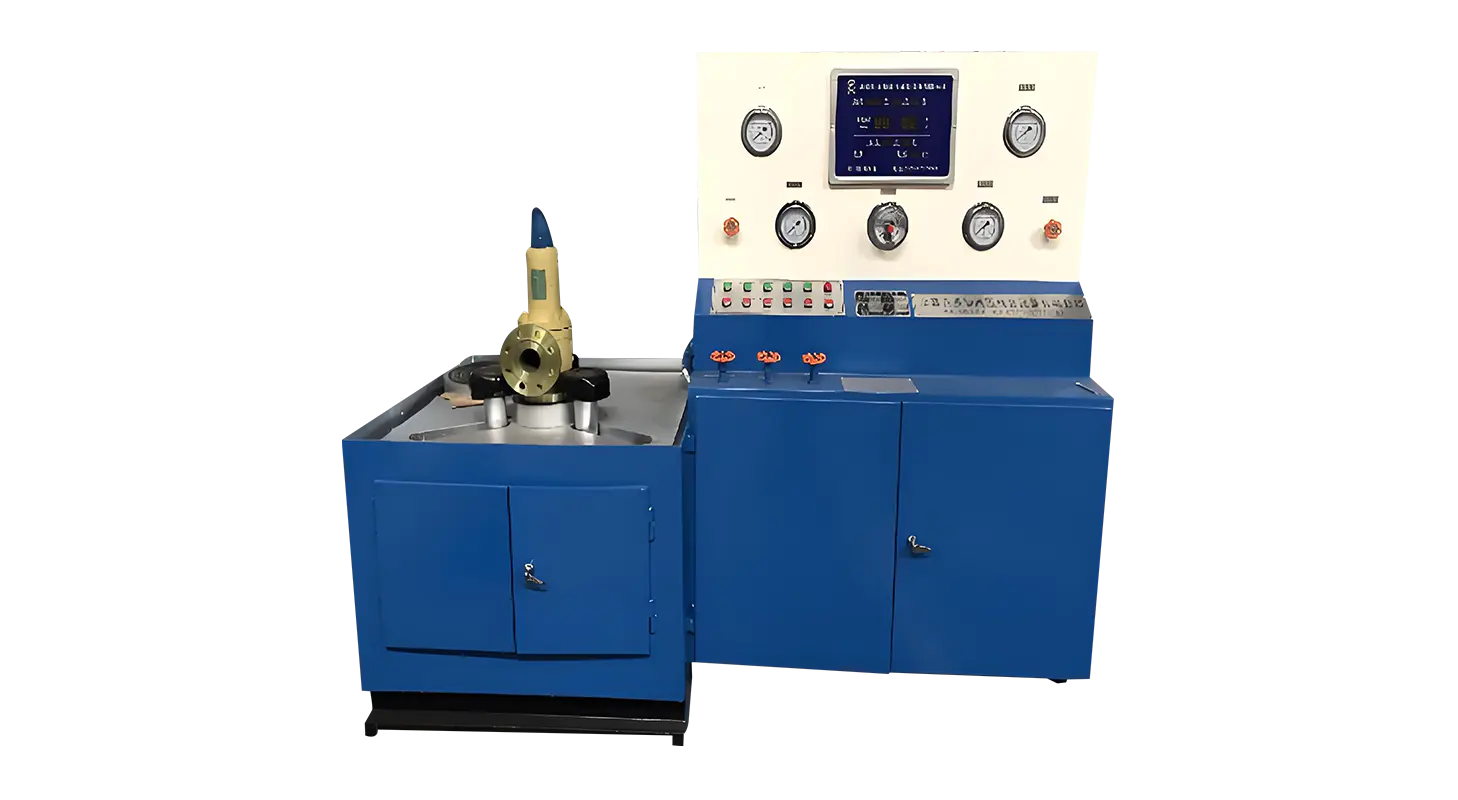
The bench’s core structure is engineered to accommodate different pressure behaviors of water and gas. A hydraulic clamping mechanism secures the test valve firmly through a flange-end positioning method. The system applies radial and axial forces uniformly through hydraulic cylinders, ensuring that the valve remains stable during both water and gas tests. This method avoids external mechanical stress that could alter test readings, maintaining accuracy across varying media types.
The clamping and sealing design also helps prevent medium leakage between the valve and test interface, which is essential when switching from water to gas testing. Since gases are more compressible than liquids, even small leaks could impact readings. The precise machining of sealing surfaces and controlled hydraulic pressure ensure effective isolation during both modes of operation.
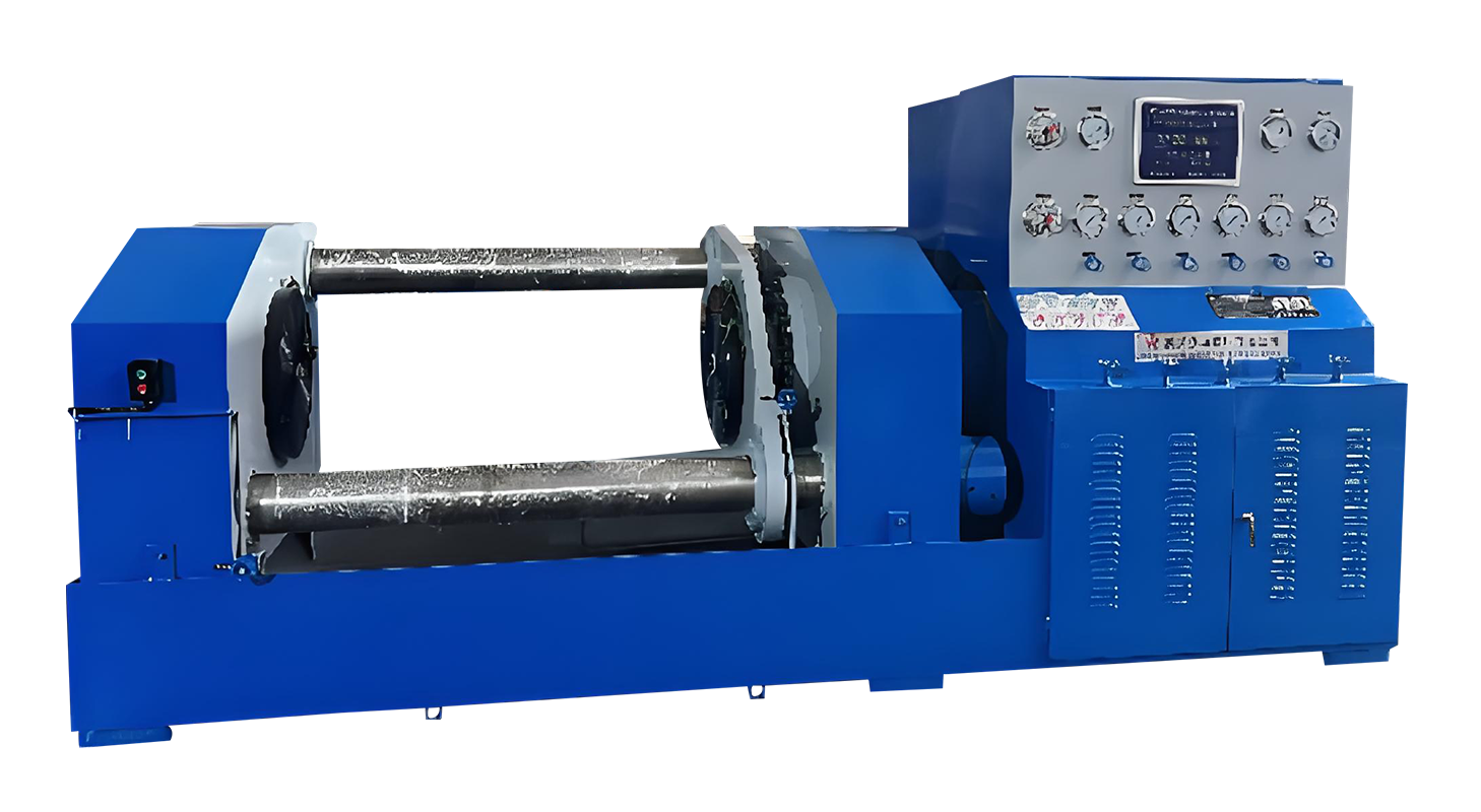
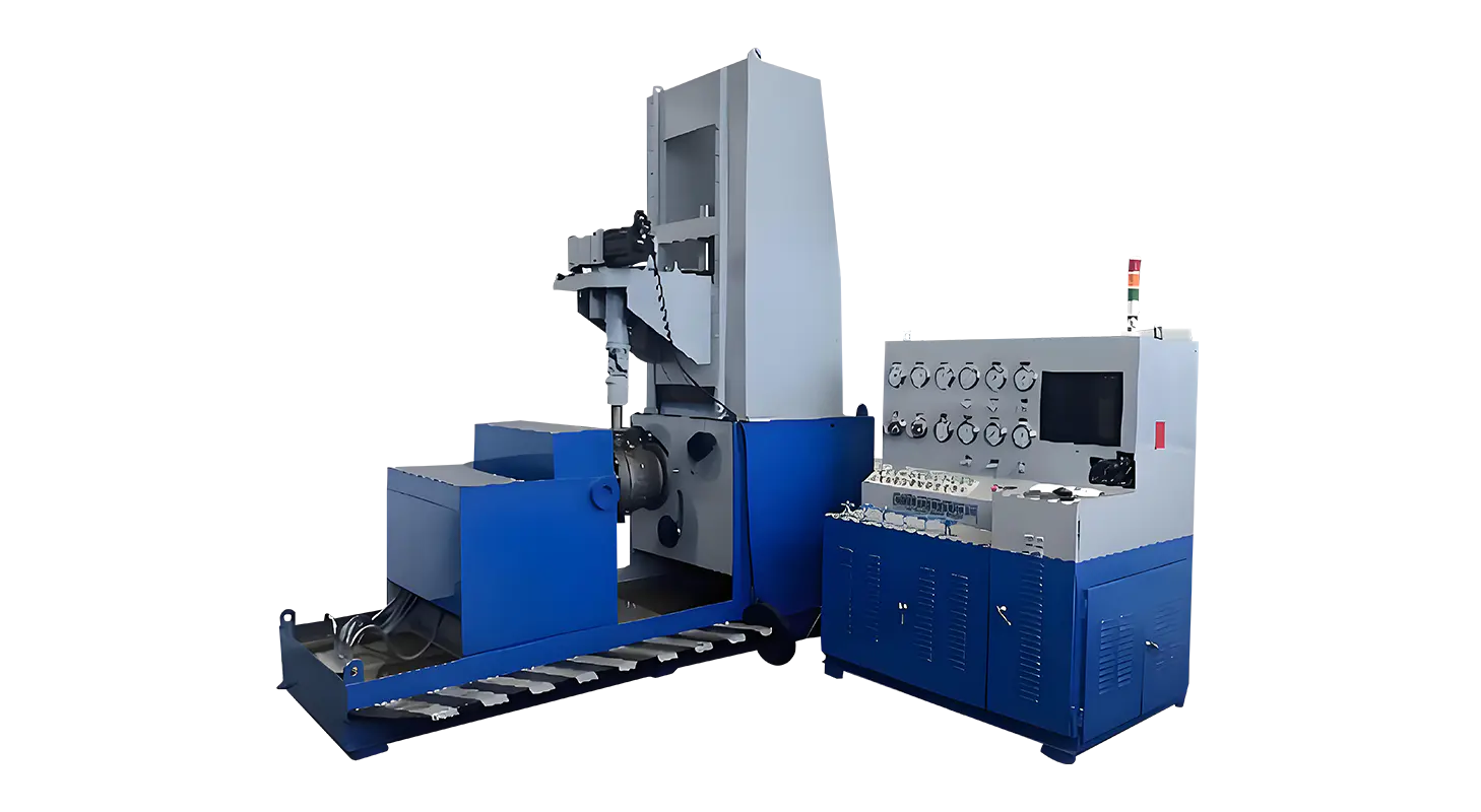
The Hydraulic Valve Test Bench includes a multi-stage hydraulic system that manages clamping, pressurization, and pressure release. For water testing, it features a low-pressure pump for rapid filling and a high-pressure pump for gradual pressure increase. Once the target value is reached, the system automatically holds pressure for the duration of the test. This function helps detect even minor sealing issues while avoiding sudden fluctuations that could affect the results.
When switching to gas testing, the built-in gas booster unit is activated. A pre-stabilization tank maintains consistent input pressure—typically between 3.0 to 5.0 MPa—allowing the gas booster to operate efficiently. This configuration ensures smooth and controlled pressure buildup, avoiding rapid surges that might damage the valve or compromise measurement accuracy.
One of the key features that makes the Relief Valve Test Bench suitable for dual media testing is the integrated pipeline control valve system. Operators can easily switch between water and gas without manual disassembly or complicated setup changes. Dedicated inlet and discharge valves control the flow path for each medium, simplifying the transition process.
Safety mechanisms are built into the design to prevent premature release or accidental pressure buildup. The system includes a zero-pressure safety protection feature that allows clamping jaws to open only after the internal cavity has completely depressurized. This ensures that the valve can be removed safely after testing. Additionally, multiple pressure gauges monitor high, medium, low, and micro pressure ranges, giving operators full visibility into each stage of testing.
During actual operation, dual media testing begins with water pressure inspection. The valve is mounted, and the hydraulic clamping force is adjusted based on the test requirements. Water is introduced into the system, and the pressure is gradually increased. Once the valve opens, the operator records the pressure data and observes the sealing condition. The pressure is then released, and the system is drained.
Gas testing follows with similar steps but uses compressed gas instead of water. Because gas is more sensitive to temperature and volume changes, the control system maintains stable pressure to ensure accurate measurement. The gas discharge valve is opened after testing to release pressure safely before removing the valve. Both procedures allow detailed observation of valve performance under different conditions, confirming whether it meets operational specifications.
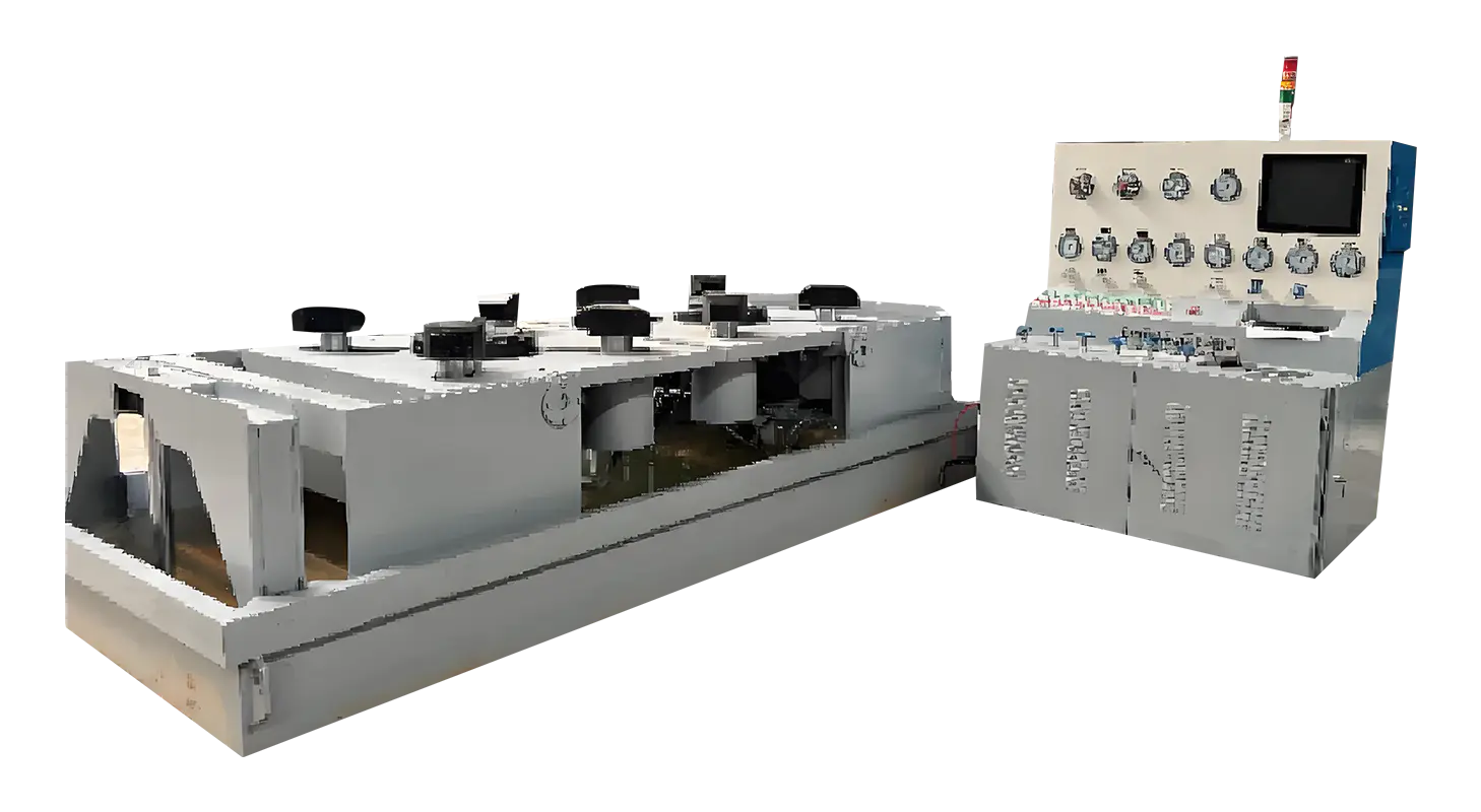
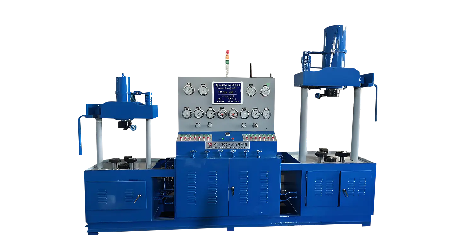
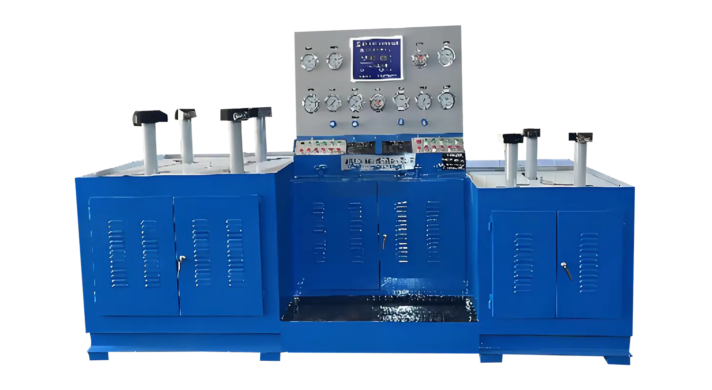
Another reason this testing system suits dual media applications lies in its modular configuration. The bench can be supplied in single or double workstation versions depending on operational needs. Facilities requiring high throughput can use a double workstation to test multiple valves simultaneously. Optional features such as safety enclosures, automatic data recording, and PLC-based control systems can further enhance functionality. These upgrades make it easier to manage test results, improve traceability, and maintain consistent quality control in large-scale operations.
Related Products
Contact us
Address
Sanqiao Industrial Zone, Oubei, Yongjia County, Zhejiang Province, China
Phone
+86-13676520568
Telephone number
+86-13676520568
Fax
products
Quick Links
QR CODE