English
 русский
 عربى
عربى
Get in touch
Get in touch
Nov 21, 2025
Ensuring operator safety and equipment stability during valve testing requires a well-designed system that incorporates multiple protection mechanisms. Both the Relief Valve Test Bench and the Hydraulic Valve Test Bench are developed to simulate working conditions for various valve types while preventing accidents that could arise from high-pressure operations. Understanding how these safety features function provides valuable insight for users seeking to perform pressure calibration, sealing inspection, and performance verification in industrial environments.
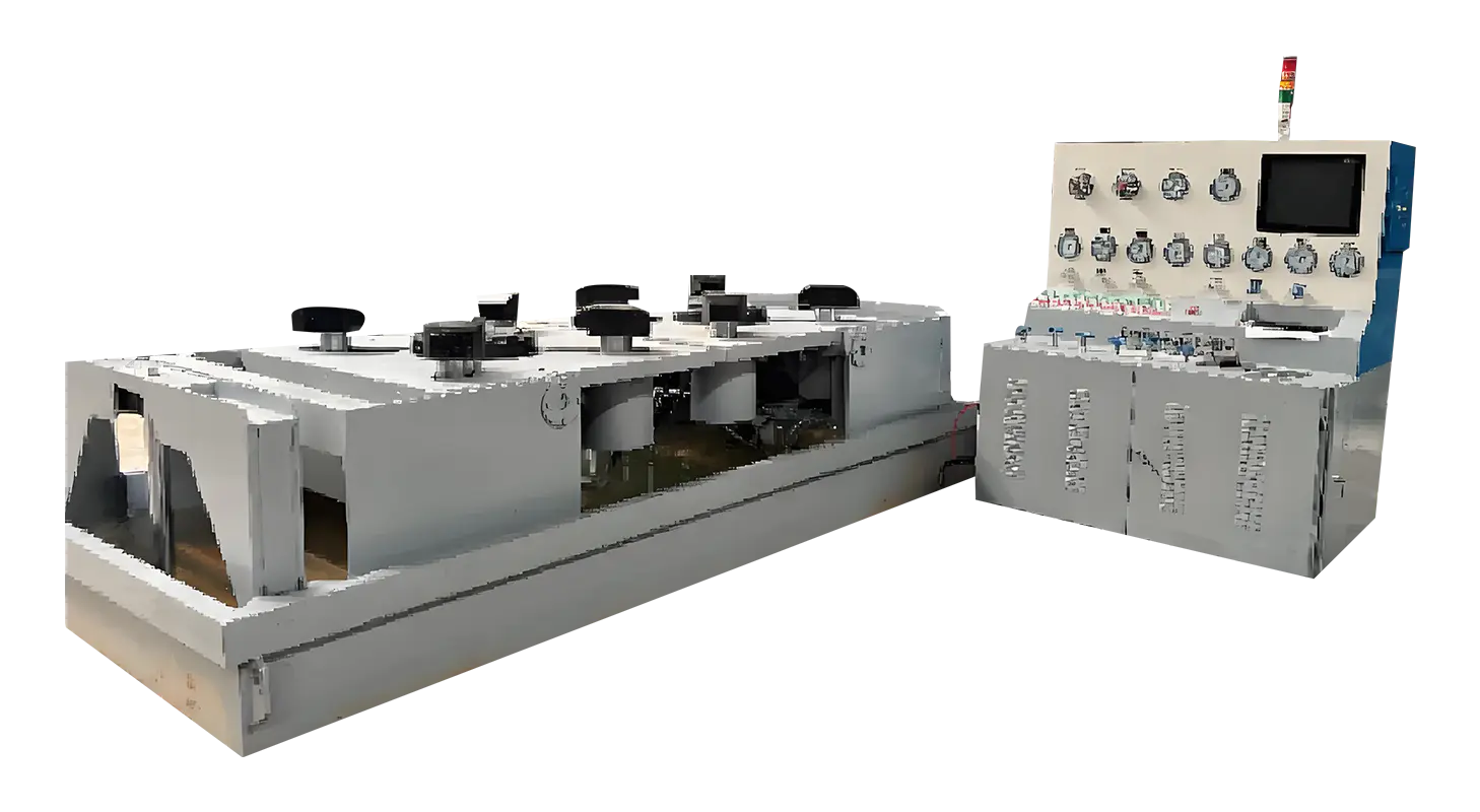
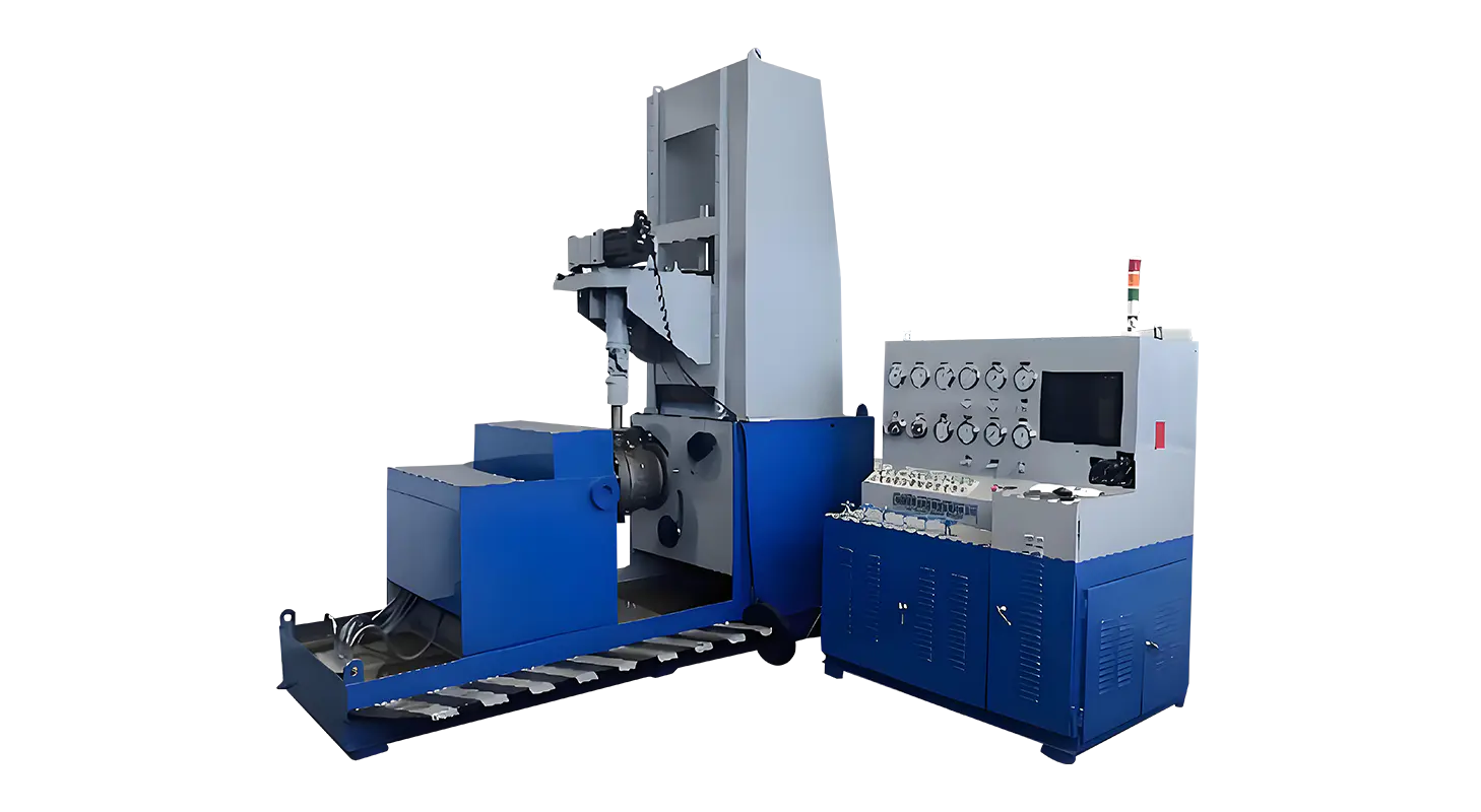
Pressure testing involves significant risk if not properly controlled, particularly when dealing with hydraulic and pneumatic systems. The Hydraulic Valve Test Bench uses a combination of mechanical and electronic safeguards to manage these risks effectively. The hydraulic clamping mechanism ensures that the valve under test is securely fixed before any pressure is applied. Hydraulic cylinders exert even force on the flange or threaded connections, preventing sudden movement or slippage during pressurization.
One of the important safety protection mechanisms integrated into the test bench is the zero-pressure interlock system. This feature ensures that the valve cannot be released from the clamping jaws until the internal cavity pressure drops to zero. It prevents accidental release while the valve is still pressurized—a critical safeguard when dealing with high-pressure water or gas tests.
The system includes a pressure monitoring circuit that continuously checks the pressure status. Only when all gauges read zero can the operator disengage the hydraulic clamping system. This measure not only protects personnel from injury but also prevents damage to valves and equipment caused by premature decompression or residual pressure. By automating the release control, the system reduces the chance of human error, which remains one of the main causes of test bench accidents.
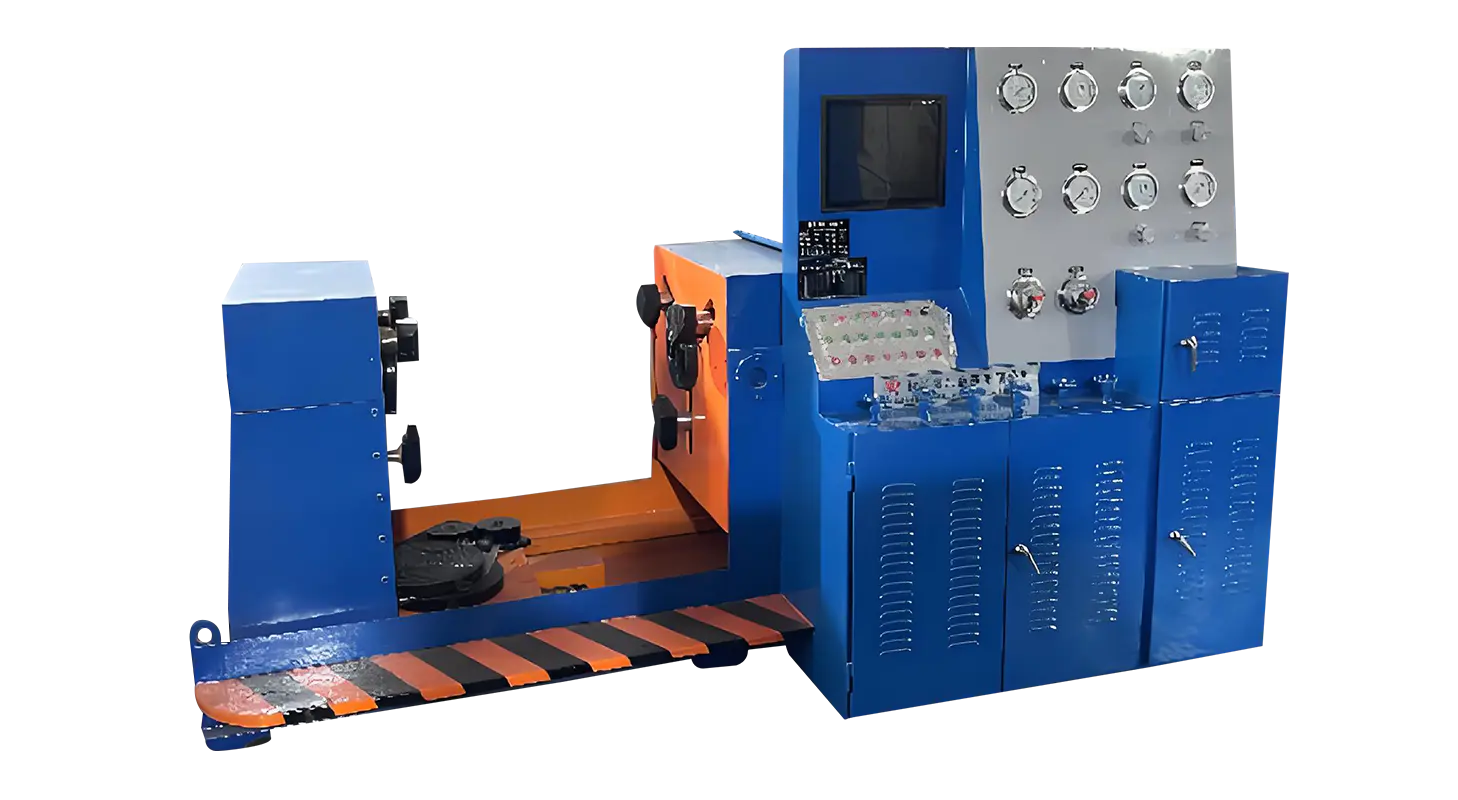
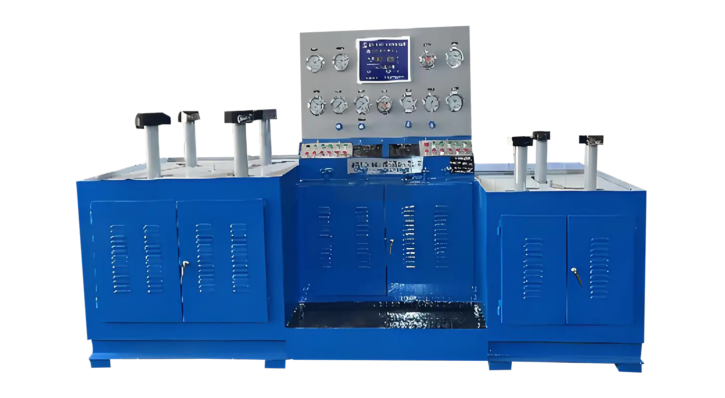
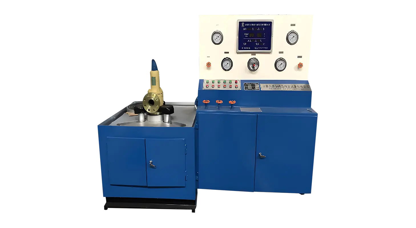
Accurate and transparent monitoring plays a central role in ensuring safety during testing. The Relief Valve Test Bench features a four-gauge pressure monitoring system that displays high, medium, low, and micro pressure values independently. This configuration allows operators to track pressure changes in real time and detect any abnormalities before they become critical.
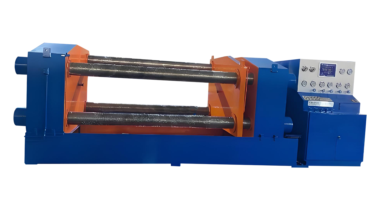
The safety of valve testing also depends on the stability of the clamping system. Hydraulic actuation allows for controlled and uniform clamping force, avoiding uneven pressure that might cause leakage or sudden release. The system’s flange-end positioning design prevents external mechanical interference, ensuring that the valve experiences only the internal test pressure.
Leak prevention is essential when switching between media such as water and gas. Any leakage during gas testing could result in dangerous pressure loss or uncontrolled gas release. The controlled hydraulic flow further ensures that the clamping force remains stable throughout the test cycle.
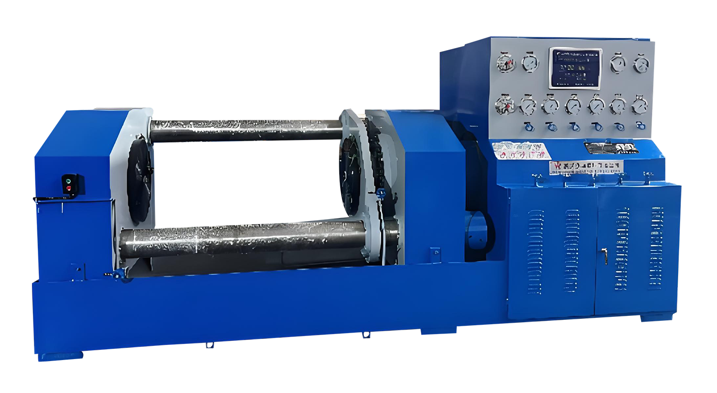
When conducting dual media testing, safety during media transition is a priority. The test bench is equipped with dedicated valves for water and gas inlet and outlet, allowing secure switching between media without disassembly. The gas boosting unit, used during high-pressure gas testing, includes a pre-stabilization tank that maintains steady inlet pressure. Operators are advised to limit rapid charging to 5.0MPa, ensuring that the booster operates within safe parameters. This mechanism reduces the risk of shock loading or unintentional overpressure during gas-driven operations.
In addition, the automatic cutoff system activates once the desired test pressure is reached. The system holds the pressure without continuous pumping, lowering the likelihood of pressure overshoot or pump overheating. These protective features collectively ensure that the test process remains smooth and safe from start to finish.
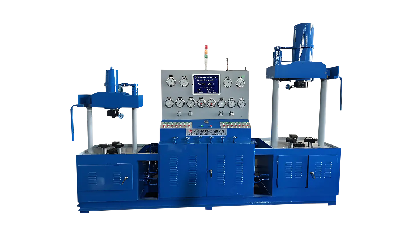
For applications that require higher safety standards, optional accessories such as protective safety doors and transparent barriers can be installed. These additions provide a physical shield between the operator and the test area, reducing exposure to potential fluid jets or flying debris in case of failure. Automatic control systems using programmable logic controllers (PLC) can further enhance operational safety by handling pressurization sequences, timing.
Automation not only increases consistency but also enforces adherence to safety protocols, as the system follows programmed limits for each test type. Data acquisition modules can record test pressure, duration, and response time, allowing traceability and early detection of irregular performance trends. These records are especially useful for facilities that must comply with strict quality and safety regulations.
Related Products
Contact us
Address
Sanqiao Industrial Zone, Oubei, Yongjia County, Zhejiang Province, China
Phone
+86-13676520568
Telephone number
+86-13676520568
Fax
products
Quick Links
QR CODE