English
 русский
 عربى
عربى
Get in touch
Get in touch
Jan 02, 2026
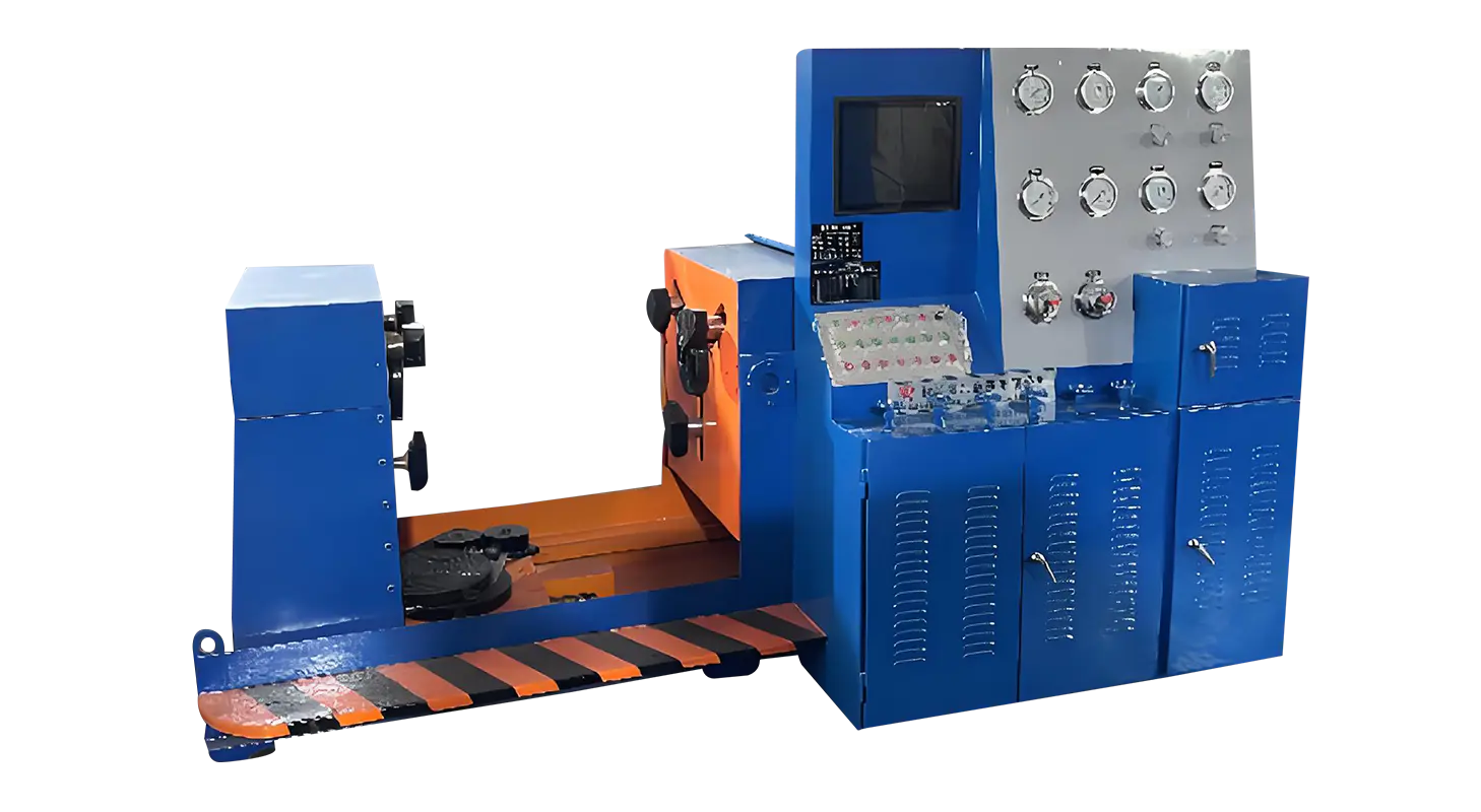
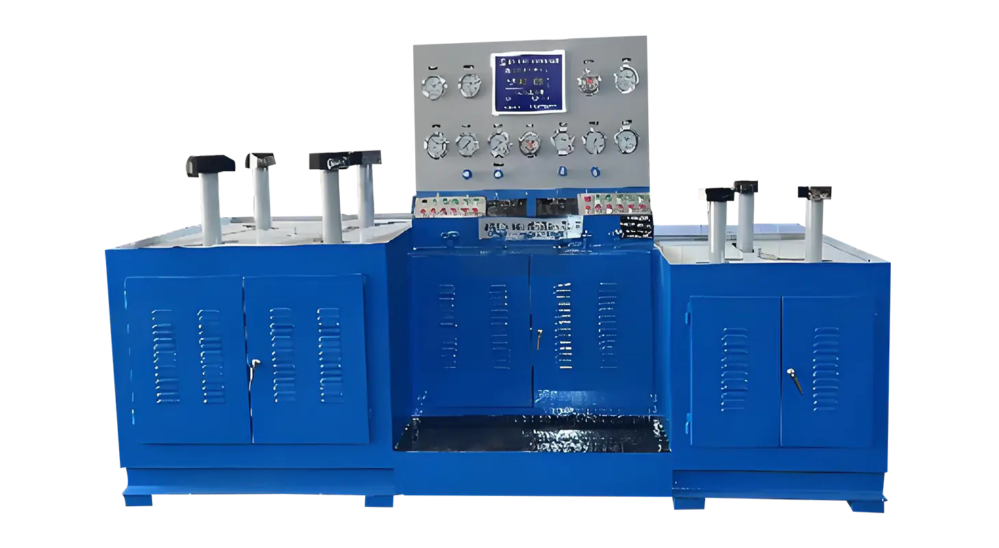
Growing attention toward multi-media inspection has made technicians examine how a Safety Valve Test Bench and a Control Valve Test Bench handle both gas and water during routine testing. As different industries rely on valves that function under varied operating environments, understanding how one piece of equipment supports two testing media helps users determine whether their current setup can meet shifting inspection needs. Many facilities now prefer benches that allow switching between liquids and gases without complex system changes, ensuring that each valve type is assessed under realistic conditions.
Supporting two testing media requires a structured flow path that separates water and gas channels. A typical setup uses designated inlet valves for each medium, allowing operators to choose which path to activate without modifying hardware connections.
Control valves built into the bench isolate the unused medium, preventing crossover and helping maintain consistent pressure behavior. This arrangement avoids unintended mixing and reduces the need for manual intervention during transitions.
For users frequently alternating between water and gas, this separation streamlines operation and shortens preparation time, especially when a series of valves must be tested in different modes.
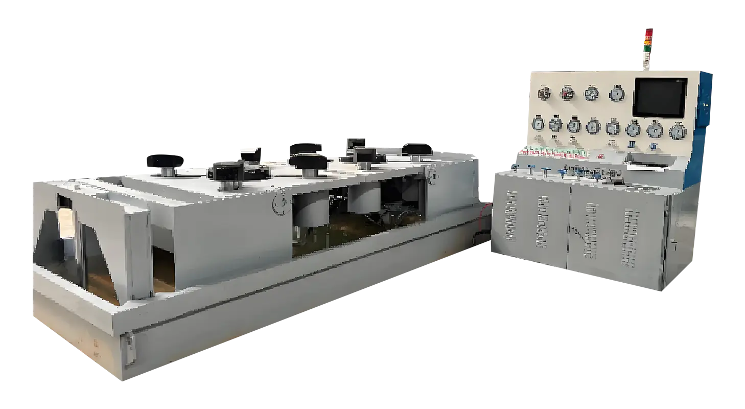
Water testing often focuses on structural integrity and sealing performance. To support this, the test bench usually combines a low-pressure rapid pump with a high-pressure slow-increase pump.
The rapid pump fills the system quickly to a basic level, allowing the operator to reach an initial stage without delay. Once the slow-increase pump engages, pressure rises steadily, giving technicians more control during final adjustments and hold durations.
This staged approach helps avoid sudden pressure spikes that could affect measurement accuracy. When the required pressure is reached, the bench shifts into a timed pressure-holding mode, allowing operators to check leakage behavior or observe small changes in sealing conditions.
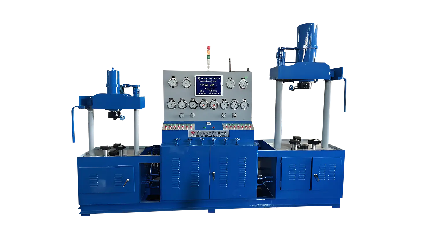
Gas testing introduces different challenges because gases compress, expand, and respond to pressure differently from water. A gas-boosting system, often supported by a pre-stabilization tank, helps create a stable flow before the booster pump pushes pressure higher.
The pre-stabilization tank helps ensure the gas enters the booster at a consistent range, typically around 3–5 MPa, which is adequate for the pump to continue building pressure. Limiting rapid charging prevents excessive load that could affect the equipment.
Once pressure reaches the required level, the system maintains a hold state similar to water testing, allowing inspectors to observe leak points or structural responses under gas-based conditions.
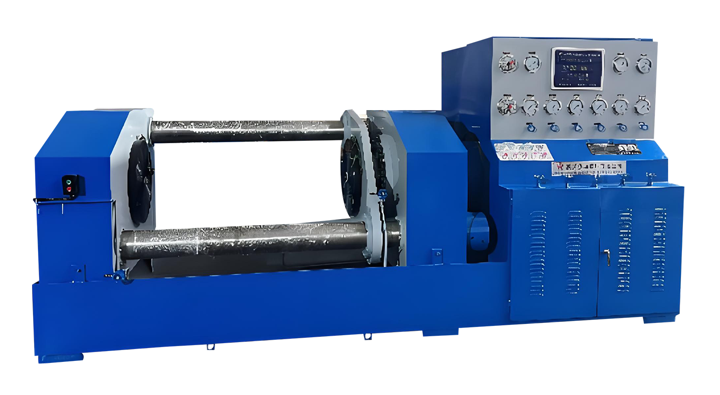
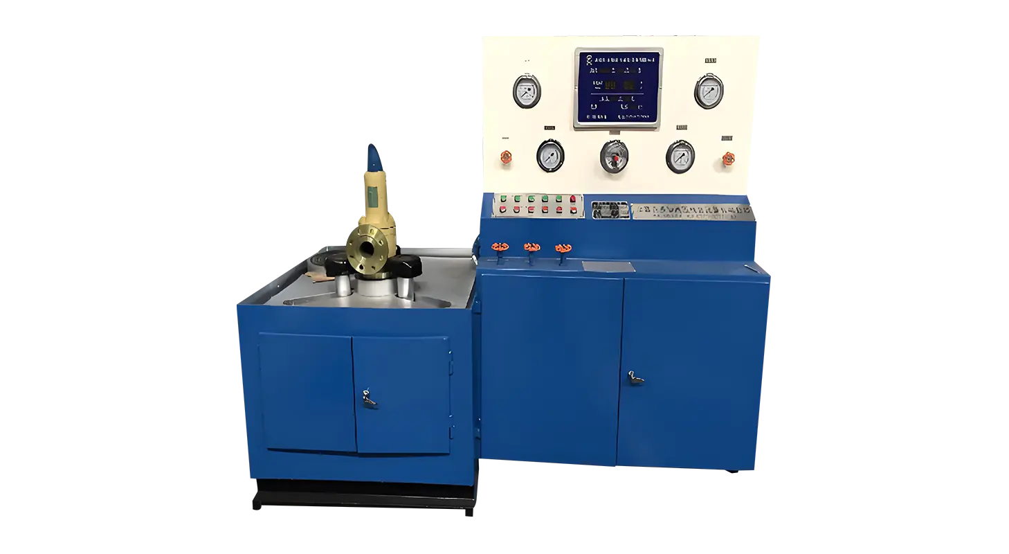
Whether a valve is tested with water or gas, its mounting stability greatly affects test outcomes. The bench’s clamping mechanism—often driven by hydraulic cylinders—positions the jaws around the back of the flange.
This positioning secures the valve while reducing external influences that could affect sealing performance. Radial and axial adjustment capability allows the clamp to adapt to different body sizes and flange shapes, which is important when switching between water and gas tests on valves with varying structural requirements.
Uniform force distribution helps maintain consistent sealing behavior, reducing deviations between test cycles conducted under different media.
When switching between gas and water testing, consistent procedures allow inspectors to compare results more effectively. Clear steps—mounting, adjusting clamping force, setting pressure limits, and activating the appropriate pump—help operators maintain a repeatable workflow.
For water tests, the discharge valve allows pressure to drop to zero before removal. Gas tests follow a similar pattern with a gas discharge valve.
Keeping the same general sequence reduces operator confusion, especially when handling multiple valve types within the same session.
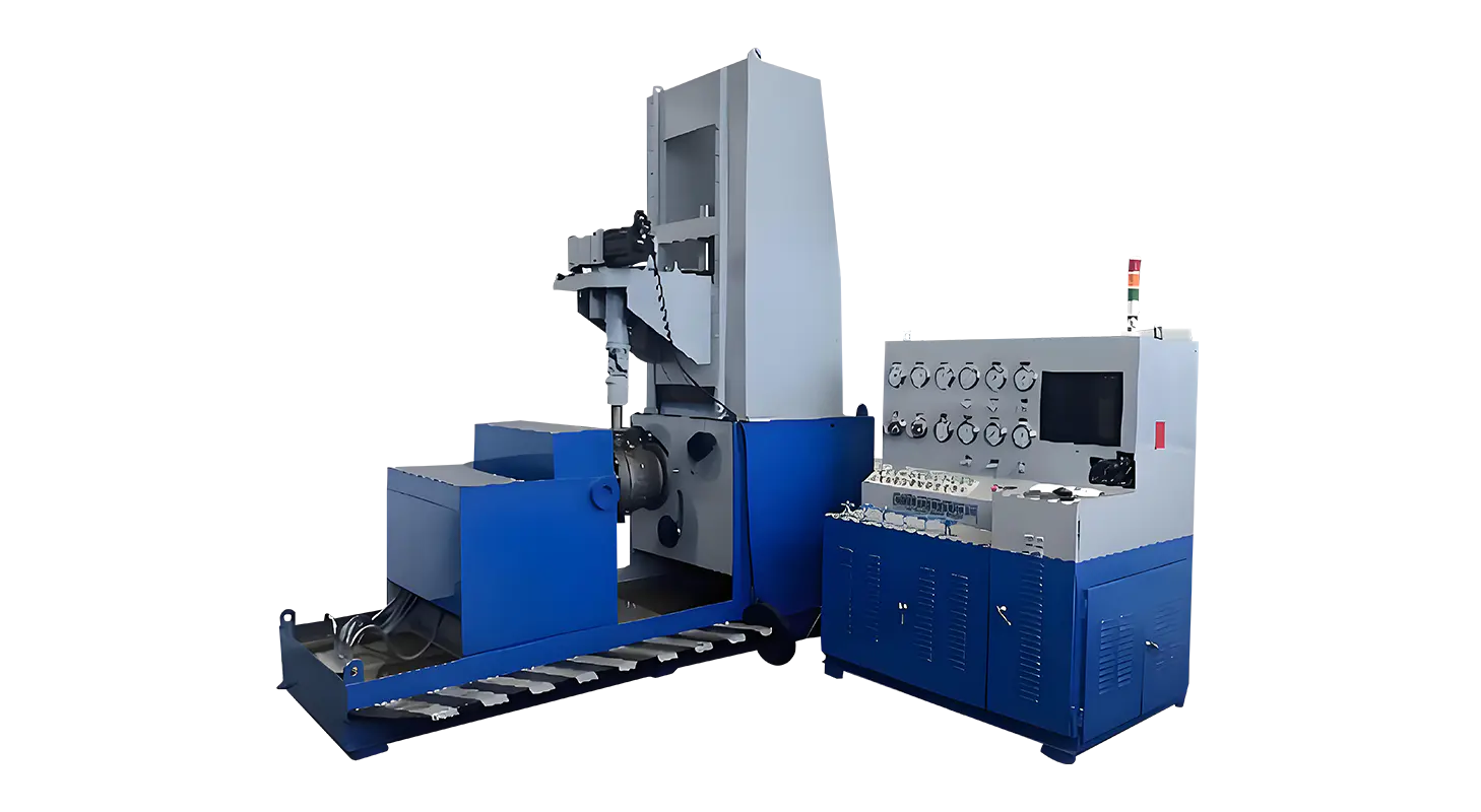
Multi-media testing is easier when the pressure display is divided into several ranges. A bench equipped with gauges for micro, low, medium, and high pressure provides users with flexibility when dealing with valves that operate under different conditions.
For instance:
Water tests may require measurement in lower pressure zones when checking basic sealing.
Gas tests may extend to higher pressure levels, demanding a gauge that remains readable and stable even under elevated conditions.
This setup helps technicians monitor changes more accurately, particularly when working with valves designed for specialized flow control or unique structural properties.
Supporting both media means the system must ensure complete pressure release before the valve is removed. The bench includes a zero-pressure protection mechanism that prevents clamp release when internal pressure remains above zero.
This safeguard protects operators and prevents accidental force being applied to the valve body.
Related Products
Contact us
Address
Sanqiao Industrial Zone, Oubei, Yongjia County, Zhejiang Province, China
Phone
+86-13676520568
Telephone number
+86-13676520568
Fax
products
Quick Links
QR CODE