English
 русский
 عربى
عربى
Get in touch
Get in touch
Dec 12, 2025
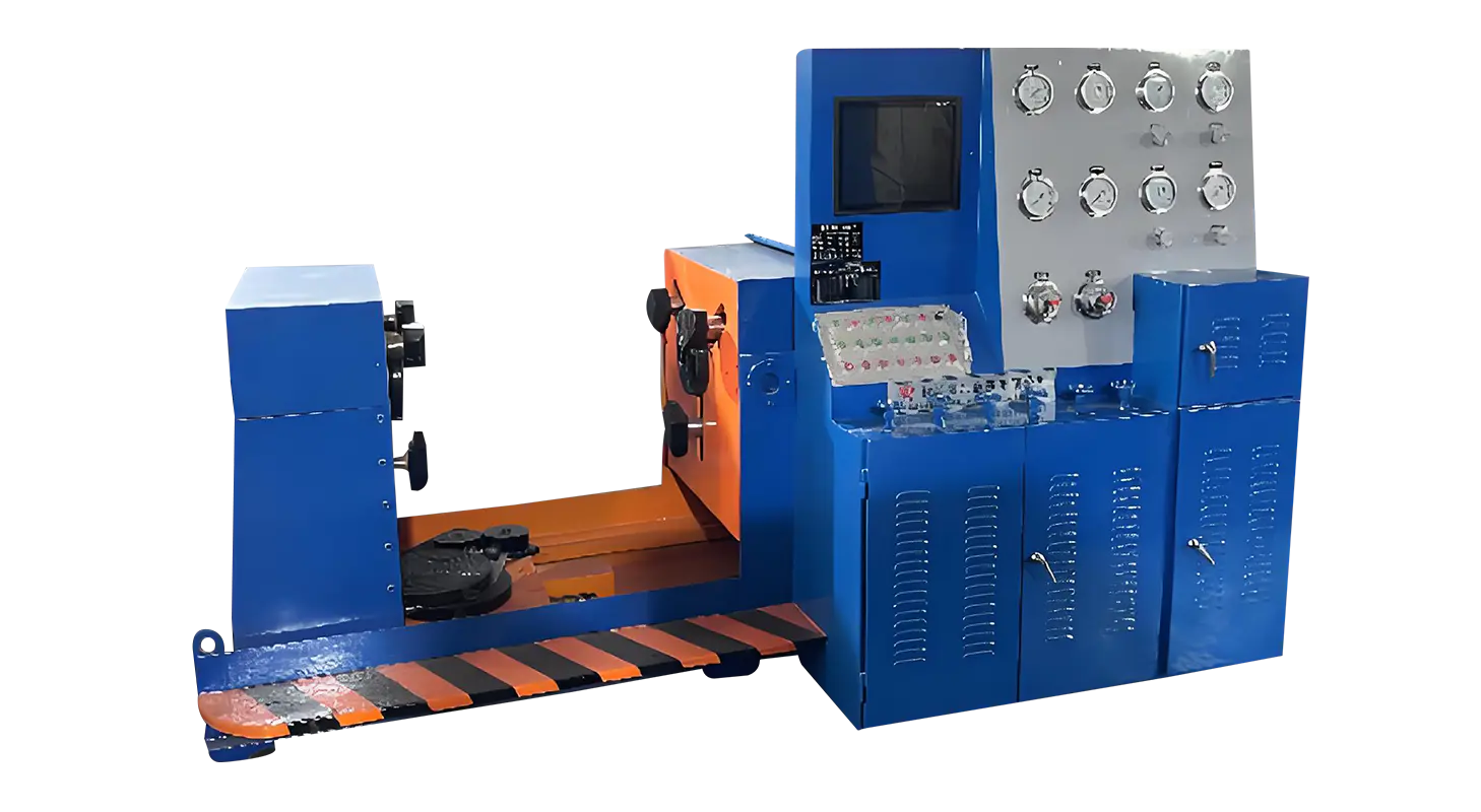
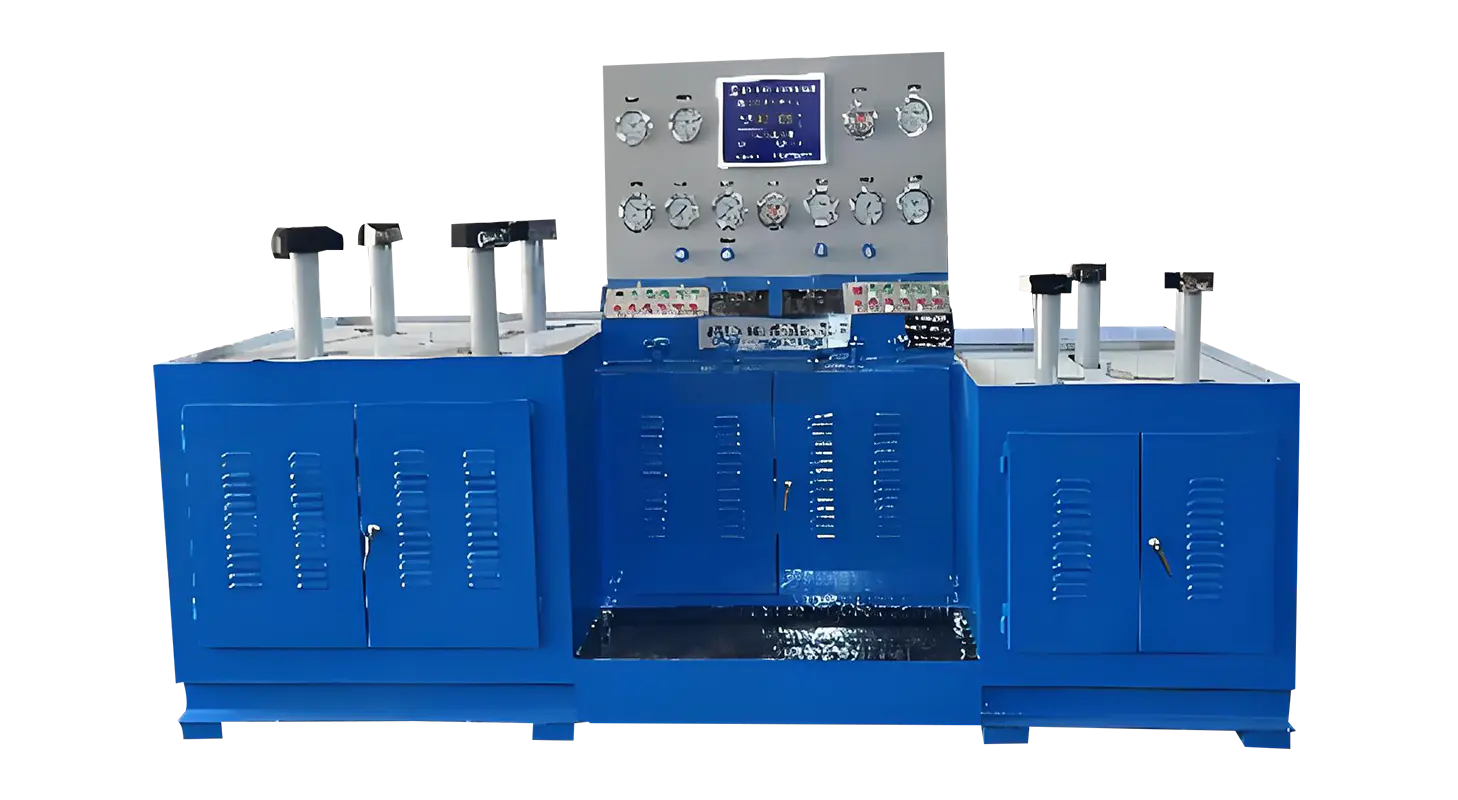
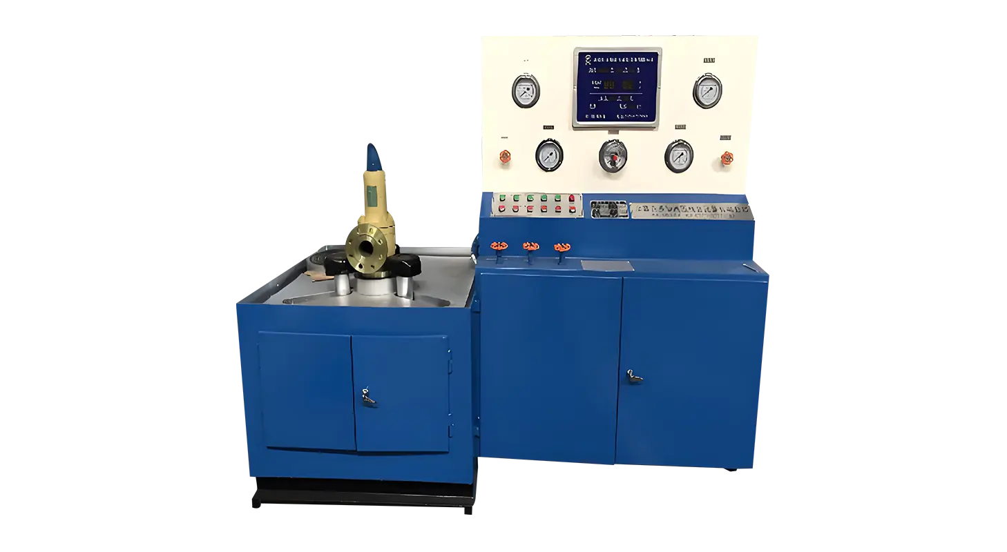
Growing demand for accurate inspection and stable testing conditions has drawn attention to tools such as a Safety Valve Test Bench and a Control Valve Test Bench, especially in environments where valves must function across different pressures and media. As technicians look for ways to handle pressure transitions without abrupt changes, many are evaluating how modern test benches are structured to maintain steady control throughout every stage of testing

Smooth pressure transition begins with how the valve is secured. If the clamping force is uneven or changes during the test, the valve may shift slightly and influence the pressure curve. Modern systems address this by using hydraulic cylinders to apply radial and axial force in a more uniform way. The clamping jaws typically hold the back of the flange directly, allowing the sealing surface to maintain its natural state without unnecessary interference from external forces.
This approach is particularly beneficial when switching between low, medium, and higher pressure ranges. A stable mechanical foundation helps prevent fluctuations caused by vibration, misalignment, or clamp slippage. Operators also gain more predictability in pressure buildup, making it easier to observe leakage points or valve movement.
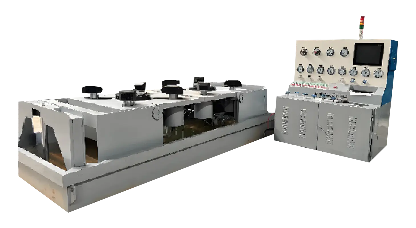
A key contributor to smooth pressure transition is the combination of different pumping systems within the test bench. Water-based tests often use two pumps:
• A rapid-fill pump for quick initial pressurization
• A slow-increase high-pressure pump for steady progression toward the test value
This layered setup helps technicians avoid abrupt jumps in pressure, especially when testing valves with narrow tolerances. After reaching the set pressure, the system generally shifts into a pressure-holding mode. This controlled pause gives operators time to check for sealing performance or structural behavior without manually adjusting valves or pump output.
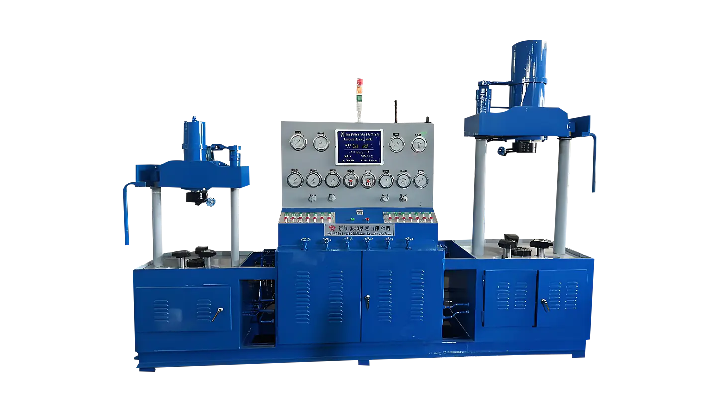
Gas-based tests take a similar approach but rely on a booster system connected to a pre-stabilization tank. Charging the tank to a moderate range keeps the pressure stable enough for the booster to operate effectively. This prevents sudden surges and allows pressure to be increased in a more predictable manner.
Facilities often need to switch between hydrostatic and pneumatic testing. Smooth transitions between media depend heavily on how the test bench handles inlet valves, discharge valves, and internal routing. Systems equipped with separate control valves for water and gas help technicians avoid cross-media interference, which could otherwise affect the test sequence.
During water tests, operators typically close the gas inlet and open the water discharge as part of the preparation phase. For gas tests, the process reverses, ensuring only one medium enters the valve at a time. By isolating each path clearly, the test bench keeps pressure transitions controlled and reduces the chance of trapped air or residual water causing inconsistent readings.
Media recyclability—such as using water repeatedly through filtration—also helps keep operation steady, though the primary benefit lies in maintaining consistent flows rather than producing abrupt changes.
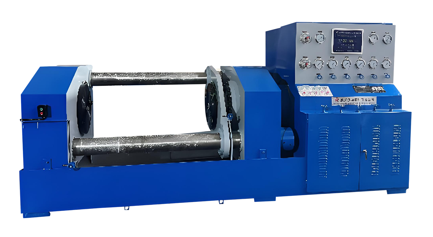
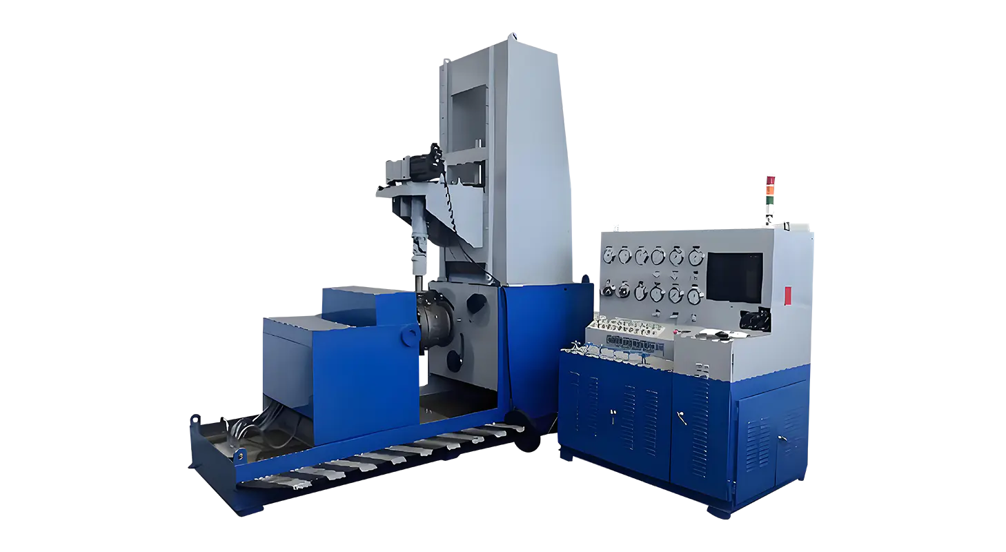
Pressure transitions depend not only on pumps and clamping but also on the accuracy of measurement tools. Many inspection systems use four separate gauges:
• High pressure
• Medium pressure
• Low pressure
• Micro pressure
Each gauge covers a distinct range, allowing operators to choose the appropriate scale based on the valve type. This prevents overreliance on a single gauge that may not show subtle changes clearly. When a technician can observe the pressure rise with precision, it becomes easier to apply gradual adjustments, verify plateau points, or detect small drops that indicate leakage.
By having each range dedicated to a specific segment of the test, the bench reduces misinterpretation or sudden corrections that could disrupt the transition process.
Smooth pressure transition does not end when the valve reaches the test value. Returning to zero pressure must also be controlled to prevent sudden release that may destabilize the components. Systems with zero-pressure safety protection only allow the clamping jaws to open once internal pressure reaches zero. This ensures the unloading process follows a consistent routine, reducing risks to both the operator and the valve structure.
This feature also encourages better habits in daily operation. Technicians can focus on observing the pressure decay curve rather than rushing to release the fixture, which supports more stable practice in workflow and helps prevent errors caused by premature handling.
Automation is becoming increasingly common in test bench configurations. PLC-based systems with data logging functions help stabilize pressure transitions by regulating pump activation, valve switching, and holding times. Rather than relying on manual timing, automated sequences maintain the same settings across repeated tests, which improves continuity.
Digital acquisition offers clearer pressure transition curves, helping users identify any irregular rise or decline. This visibility is especially helpful when evaluating valves with specific response characteristics, such as spring-loaded safety valves or modulating control valves. Automation does not replace manual oversight but supports it by giving each test a structured flow.
Related Products
Contact us
Address
Sanqiao Industrial Zone, Oubei, Yongjia County, Zhejiang Province, China
Phone
+86-13676520568
Telephone number
+86-13676520568
Fax
products
Quick Links
QR CODE